Technical Information · issue 26 of 2002
New chainsaws STIHL MS 270 and MS 280
Models with QS chain brake system
IssueTI 26/2002
Engine family 1133
Full text
Page 1 of 14
Text of page 1 — search, copy, screen readers
Technical Information

                                                                                           26.2002
New chainsaws STIHL MS 270 and MS 280 – Series 1133

Contents
1.   Technical description
2.   Specifications

3.   Service accessories and special tools

4.   Service notes
5.   Spare parts

                                                   S 270 C mit Kettenschnellspannung, Elastostart und
                                                   Dekompressionsventil
                                                   S 270 C mit Kettenschnellspannung, Elastostart und
                                                   Dekompressionsventil
                                                   S 270 C mit Kettenschnellspannung, Elastostart und
                                                   Dekompressionsventil

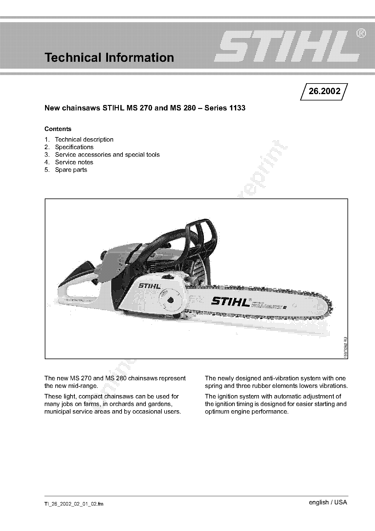
The new MS 270 and MS 280 chainsaws represent      The newly designed anti-vibration system with one
the new mid-range.                                 spring and three rubber elements lowers vibrations.

These light, compact chainsaws can be used for     The ignition system with automatic adjustment of
many jobs on farms, in orchards and gardens,       the ignition timing is designed for easier starting and
municipal service areas and by occasional users.   optimum engine performance.

TI_26_2002_02_01_02.fm                                                                     english / USA
Page 2 of 14
Text of page 2 — search, copy, screen readers
Page 2                                                                                   Technical Information 26.2002

The MS 270 and MS 280 are available in two                         Ignition
versions (not in all markets):
                                                                   .     Ignition system with automatic adjustment of the
.     Standard version                                                   ignition timing
.     MS 270 C and MS 280 C with ElastoStart, chain                Diaphragm carburetor with full-throttle partially
      quick tensioning, decompression valve and QS                 fixed nozzle, part-throttle nozzle and contingent
      chain brake, depending on the market versions                idling
      offered
                                                                   .     Limiter caps limit the adjustment range for the
                                                                         high speed adjusting screw and low speed
1.      Technical description                                            adjusting screw (approx. 3/4 turn) to ensure
                                                                         greater operational reliability and compliance
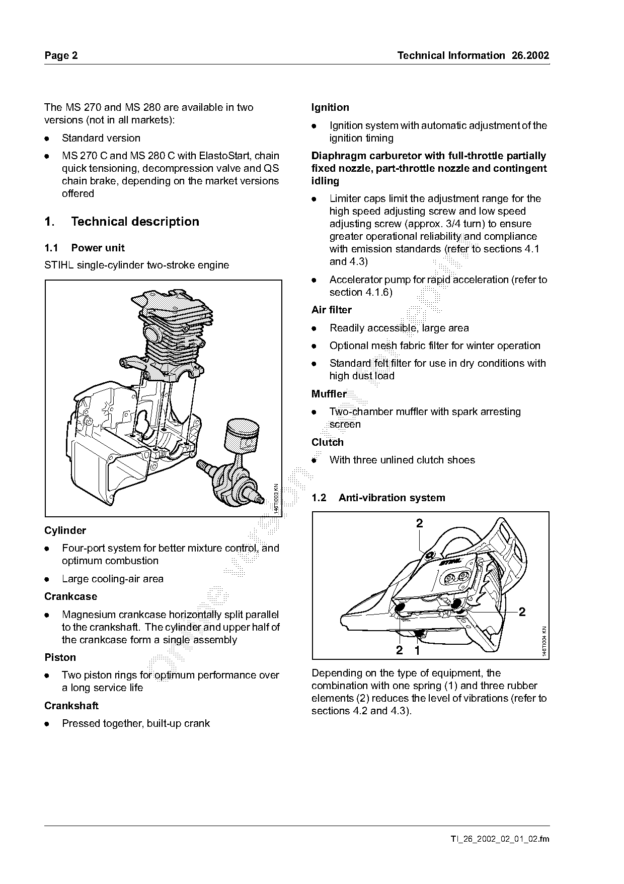
1.1     Power unit

                                                                         with emission standards (refer to sections 4.1

STIHL single-cylinder two-stroke engine                                  and 4.3)
                                                                   .     Accelerator pump for rapid acceleration (refer to
                                                                         section 4.1.6)

                                                                   Air filter
                                                                   .     Readily accessible, large area

                                                                   .     Optional mesh fabric filter for winter operation
                                                                   .     Standard felt filter for use in dry conditions with
                                                                         high dust load
                                                                   Muffler
                                                                   .     Two-chamber muffler with spark arresting
                                                                         screen

                                                                   Clutch
                                                                   .     With three unlined clutch shoes
                                                     146TI003 KN

                                                                   1.2     Anti-vibration system

                                                                                             2
Cylinder

.     Four-port system for better mixture control, and
      optimum combustion

.     Large cooling-air area
Crankcase
.     Magnesium crankcase horizontally split parallel                                                                2

      to the crankshaft. The cylinder and upper half of
                                                                                                                            146TI004 KN

      the crankcase form a single assembly
                                                                                        2 1

Piston
.     Two piston rings for optimum performance over                Depending on the type of equipment, the
      a long service life                                          combination with one spring (1) and three rubber
                                                                   elements (2) reduces the level of vibrations (refer to
Crankshaft                                                         sections 4.2 and 4.3).
.     Pressed together, built-up crank

                                                                                                     TI_26_2002_02_01_02.fm
Page 3 of 14
Text of page 3 — search, copy, screen readers
Technical Information 26.2002                                                                               Page 3

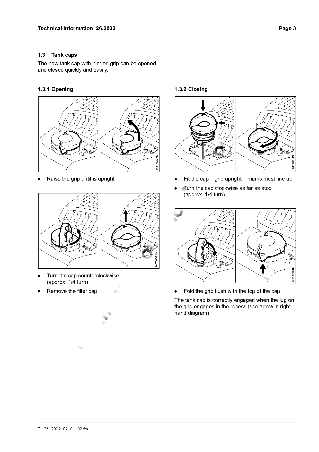
1.3     Tank caps
The new tank cap with hinged grip can be opened
and closed quickly and easily.

1.3.1 Opening                                                 1.3.2 Closing

                                                146TI005 KN

                                                                                                                146TI007 KN
.     Raise the grip until is upright                         .   Fit the cap – grip upright – marks must line up
                                                              .   fo
                                                                  Turn the cap clockwise as far as stop
                                                                  (approx. 1/4 turn).
                                         n    146TI006 KN

                                                                                                                146TI008 KN
.     Turn the cap counterclockwise

      (approx. 1/4 turn)
.     Remove the filler cap                                   .   Fold the grip flush with the top of the cap

                                                              The tank cap is correctly engaged when the lug on
                                                              the grip engages in the recess (see arrow in right-
                                                              hand diagram).

TI_26_2002_02_01_02.fm
Page 4 of 14
Text of page 4 — search, copy, screen readers
Page 4                                                                                Technical Information 26.2002

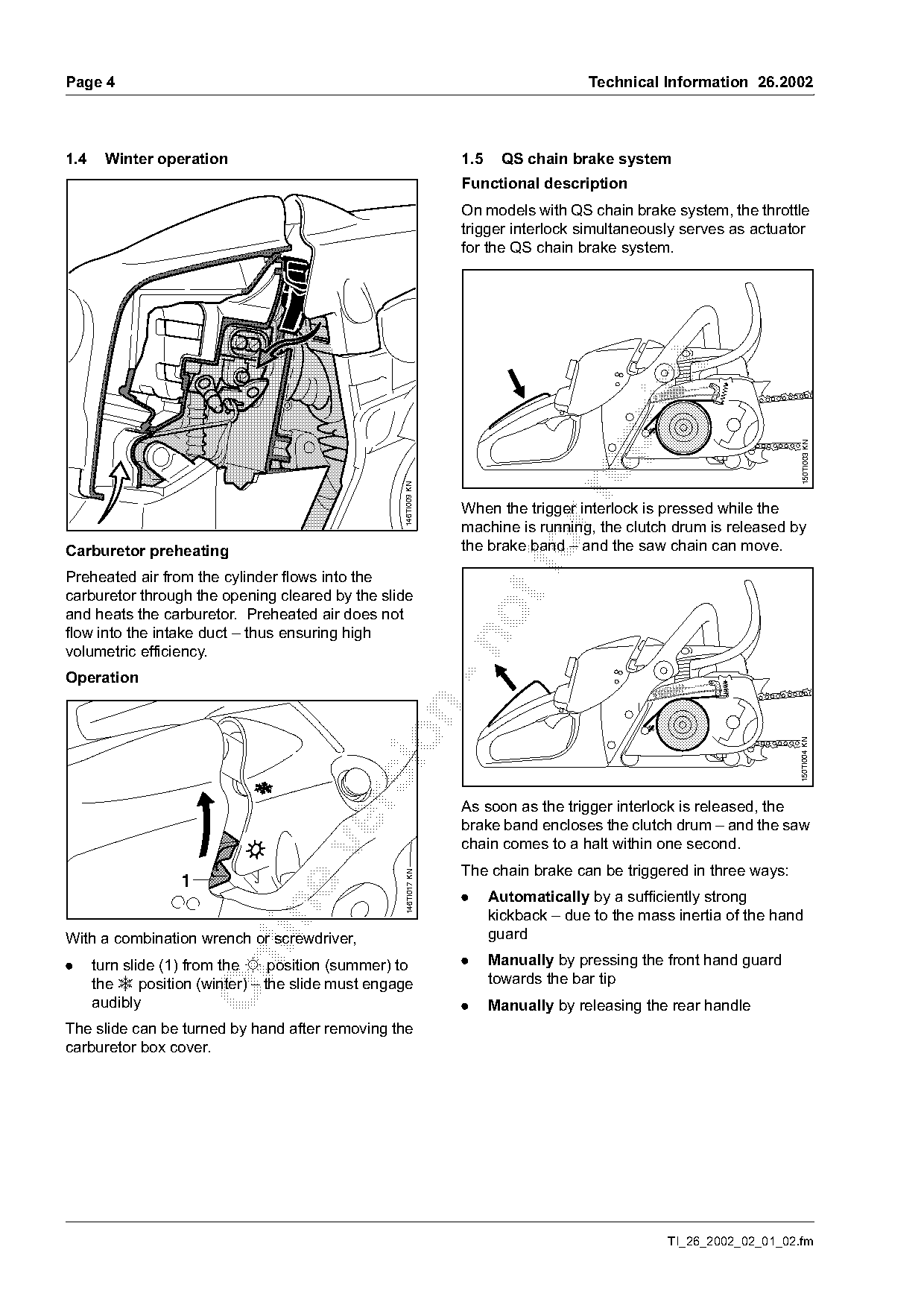
1.4    Winter operation                                           1.5    QS chain brake system
                                                                  Functional description
                                                                  On models with QS chain brake system, the throttle
                                                                  trigger interlock simultaneously serves as actuator
                                                                  for the QS chain brake system.

                                                                                                                       150TI003 KN
                                                   146TI009 KN

                                                                  When the trigger interlock is pressed while the
                                                                  machine is running, the clutch drum is released by
Carburetor preheating
Preheated air from the cylinder flows into the
                                                                  the brake band – and the saw chain can move.

carburetor through the opening cleared by the slide
and heats the carburetor. Preheated air does not
flow into the intake duct – thus ensuring high

volumetric efficiency.
Operation

                                                                                                                      150TI004 KN

                                                                  As soon as the trigger interlock is released, the
                                                                  brake band encloses the clutch drum – and the saw
                                                                  chain comes to a halt within one second.

                                                                  The chain brake can be triggered in three ways:
                                                    146TI017 KN

                   1
                                                                  .     Automatically by a sufficiently strong

                                                                        kickback – due to the mass inertia of the hand
With a combination wrench or screwdriver,                               guard

.                                                                 .     Manually by pressing the front hand guard

      turn slide (1) from the s position (summer) to
      the r position (winter) – the slide must engage                   towards the bar tip
      audibly                                                     .     Manually by releasing the rear handle
The slide can be turned by hand after removing the
carburetor box cover.

                                                                                                  TI_26_2002_02_01_02.fm
Page 5 of 14
Text of page 5 — search, copy, screen readers
Technical Information 26.2002                                                                                 Page 5

Note on chain lubrication
Chainsaws with QS chain brake system must be
lubricated with high-quality chain oil to ensure that
they operate reliably. Only STIHL Bioplus may be
used when using organic chain lubricants.
Unsuitable lubricants will lead to premature failure of
the chain brake due to resin build-up.

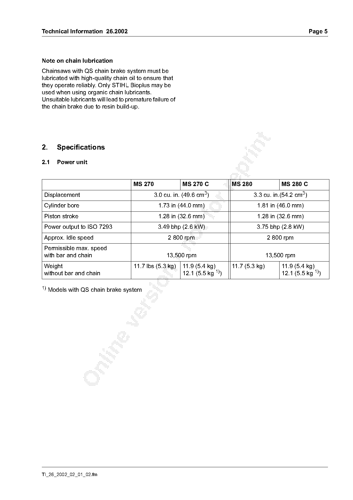
2.      Specifications

2.1     Power unit

                                     MS 270               MS 270 C           MS 280               MS 280 C

 Displacement                                 3.0 cu. in. (49.6 cm3   )               3.3 cu. in.(54.2 cm3)
 Cylinder bore                                 1.73 in (44.0 mm)                       1.81 in (46.0 mm)
 Piston stroke                                 1.28 in (32.6 mm)
                                                                fo                     1.28 in (32.6 mm)
 Power output to ISO 7293                      3.49 bhp (2.6 kW)                       3.75 bhp (2.8 kW)
 Approx. Idle speed                                 2 800 rpm                                2 800 rpm

 Permissible max. speed
 with bar and chain                                13,500 rpm                                13,500 rpm
 Weight                              11.7 lbs (5.3 kg)    11.9 (5.4 kg)      11.7 (5.3 kg)        11.9 (5.4 kg)

 without bar and chain                                    12.1 (5.5 kg 1))                        12.1 (5.5 kg 1))

1)
     Models with QS chain brake system

TI_26_2002_02_01_02.fm
Page 6 of 14
Text of page 6 — search, copy, screen readers
Page 6                                                                     Technical Information 26.2002

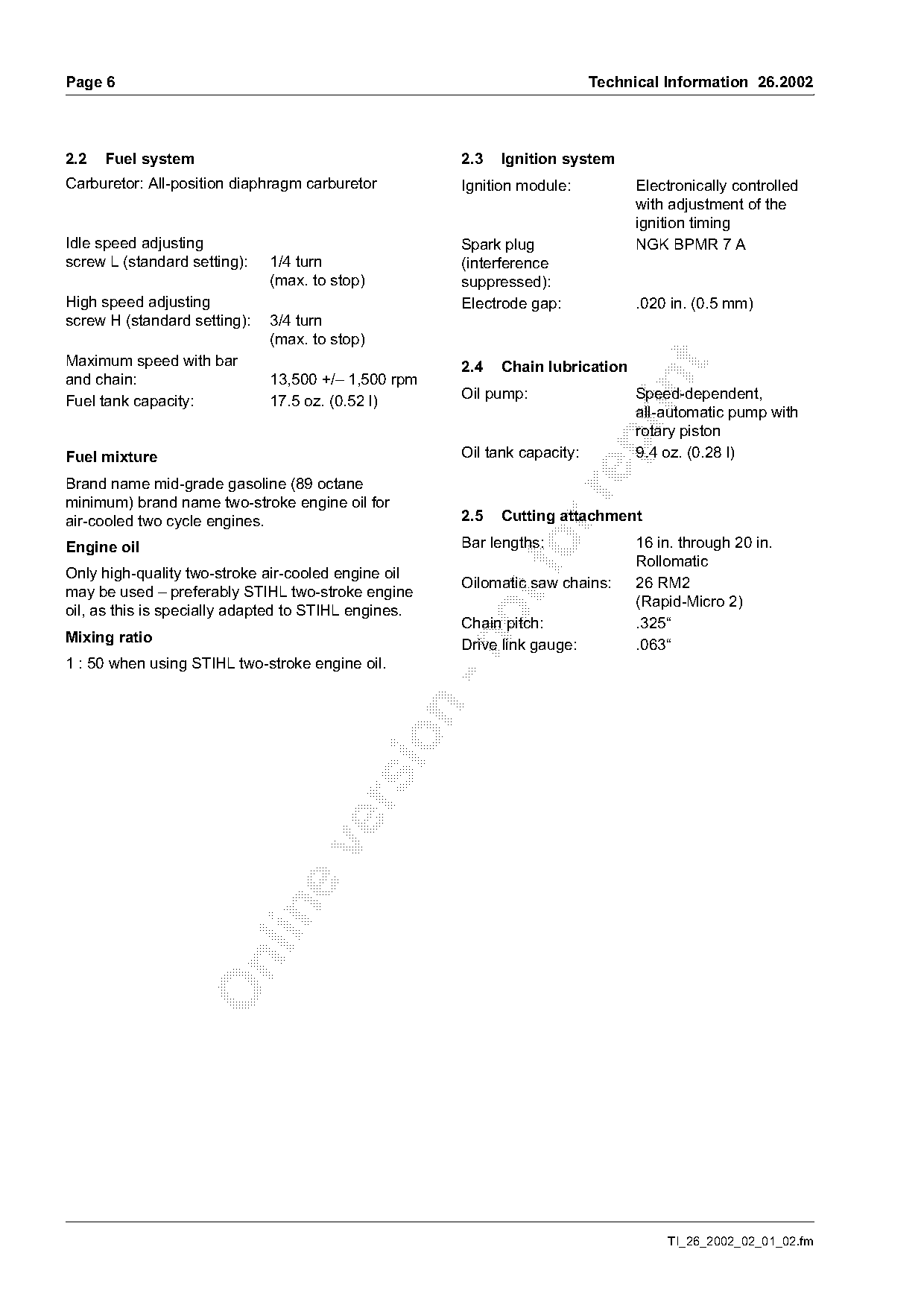
2.2   Fuel system                                     2.3   Ignition system
Carburetor: All-position diaphragm carburetor         Ignition module:           Electronically controlled
                                                                                 with adjustment of the
                                                                                 ignition timing
Idle speed adjusting                                  Spark plug                 NGK BPMR 7 A
screw L (standard setting):   1/4 turn                (interference
                              (max. to stop)          suppressed):
High speed adjusting                                  Electrode gap:             .020 in. (0.5 mm)
screw H (standard setting):   3/4 turn
                              (max. to stop)
Maximum speed with bar                                2.4   Chain lubrication

and chain:                    13,500 +/– 1,500 rpm

                                                      Oil pump:                  Speed-dependent,
Fuel tank capacity:           17.5 oz. (0.52 l)
                                                                                 all-automatic pump with
                                                                                 rotary piston

Fuel mixture                                          Oil tank capacity:         9.4 oz. (0.28 l)

Brand name mid-grade gasoline (89 octane

minimum) brand name two-stroke engine oil for
air-cooled two cycle engines.                         2.5   Cutting attachment
                                                      Bar lengths:               16 in. through 20 in.
Engine oil
Only high-quality two-stroke air-cooled engine oil
                                                              fo                 Rollomatic
                                                      Oilomatic saw chains:      26 RM2
may be used – preferably STIHL two-stroke engine
                                                                                 (Rapid-Micro 2)
oil, as this is specially adapted to STIHL engines.
                                                      Chain pitch:               .325“
Mixing ratio

                                                      Drive link gauge:          .063“
1 : 50 when using STIHL two-stroke engine oil.

                                                                                     TI_26_2002_02_01_02.fm
Page 7 of 14
Text of page 7 — search, copy, screen readers
Technical Information 26.2002                                                                                 Page 7

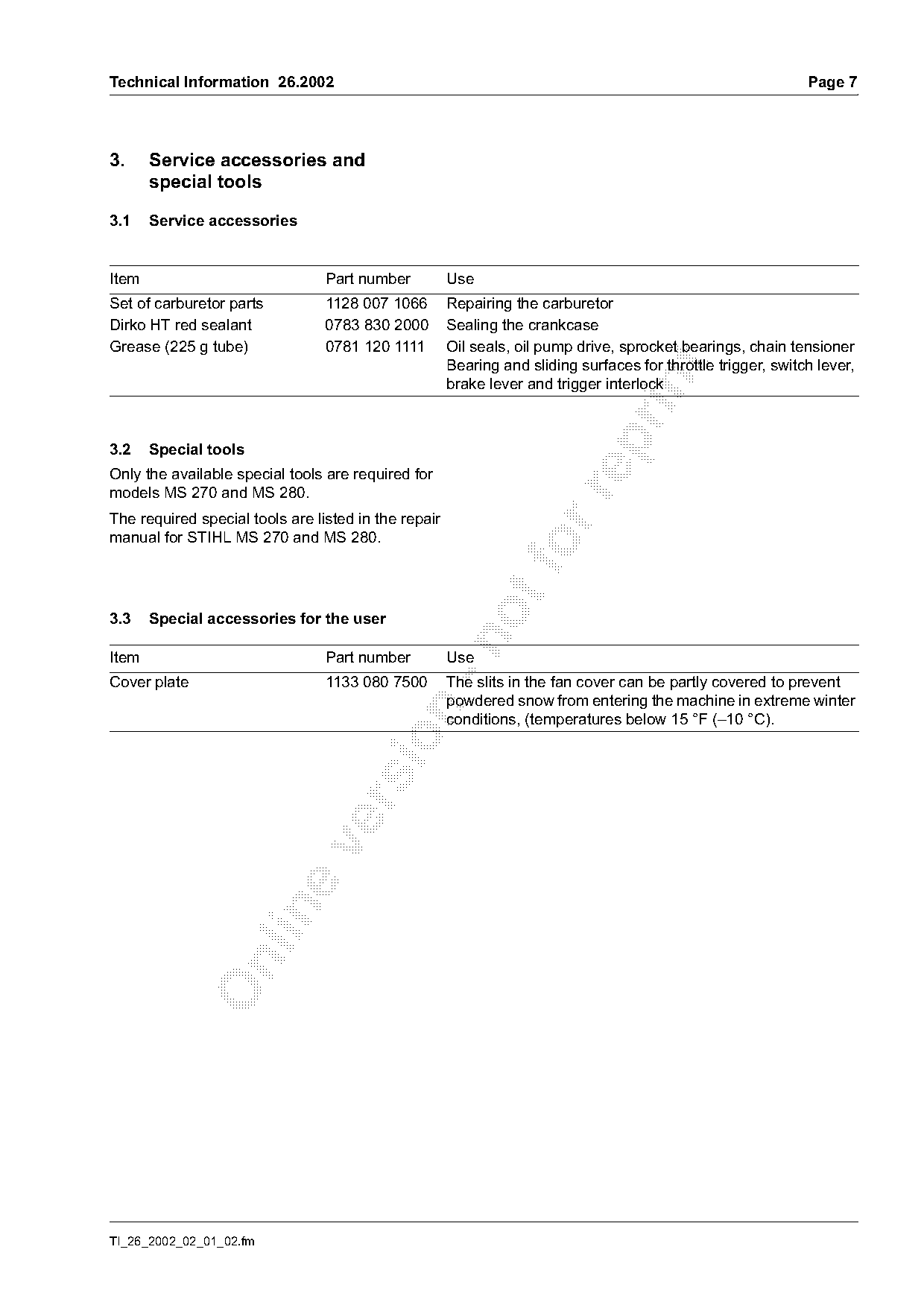
3.     Service accessories and
       special tools

3.1    Service accessories

Item                             Part number          Use
Set of carburetor parts          1128 007 1066        Repairing the carburetor
Dirko HT red sealant             0783 830 2000        Sealing the crankcase
Grease (225 g tube)              0781 120 1111        Oil seals, oil pump drive, sprocket bearings, chain tensioner
                                                      Bearing and sliding surfaces for throttle trigger, switch lever,

                                                      brake lever and trigger interlock

3.2    Special tools
Only the available special tools are required for
models MS 270 and MS 280.

The required special tools are listed in the repair
manual for STIHL MS 270 and MS 280.
3.3    Special accessories for the user

Item                             Part number          Use
Cover plate                      1133 080 7500        The slits in the fan cover can be partly covered to prevent
                                                      powdered snow from entering the machine in extreme winter

                                                      conditions, (temperatures below 15 °F (–10 °C).

TI_26_2002_02_01_02.fm
Page 8 of 14
Text of page 8 — search, copy, screen readers
Page 8                                                                                 Technical Information 26.2002

4.     Service notes                                                4.1.2 Maintenance / repair

The specific national safety regulations and the
safety instructions in the User's Manual must be
observed when starting and operating the chainsaw.

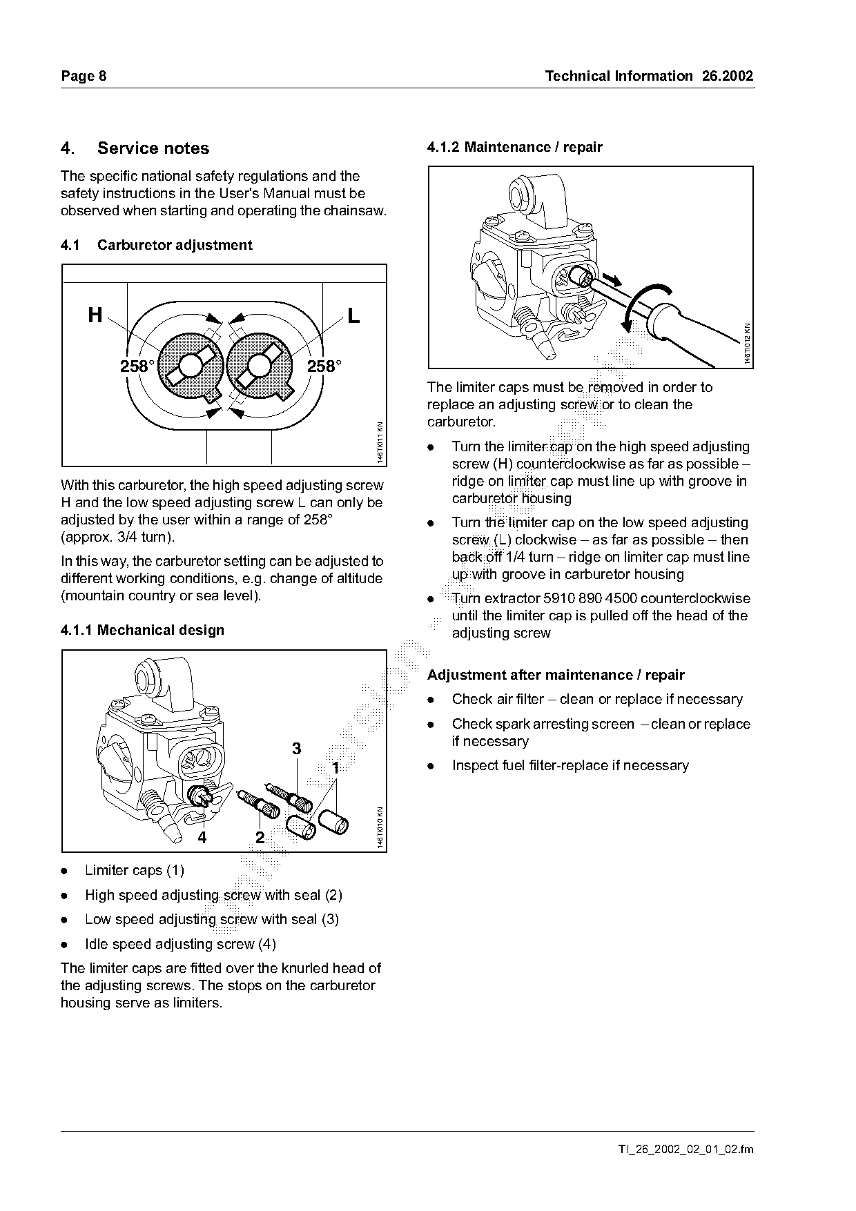
4.1    Carburetor adjustment

      H                                           L

                                                                                                                           146TI012 KN
           258°                            258°
                                                                    The limiter caps must be removed in order to
                                                                    replace an adjusting screw or to clean the

                                                                    carburetor.
                                                      146TI011 KN

                                                                    .   Turn the limiter cap on the high speed adjusting

                                                                        screw (H) counterclockwise as far as possible –
With this carburetor, the high speed adjusting screw                    ridge on limiter cap must line up with groove in
H and the low speed adjusting screw L can only be                       carburetor housing
adjusted by the user within a range of 258°                         .
                                                                        Turn the limiter cap on the low speed adjusting
(approx. 3/4 turn).                                                     screw (L) clockwise – as far as possible – then
In this way, the carburetor setting can be adjusted to                  back off 1/4 turn – ridge on limiter cap must line
different working conditions, e.g. change of altitude                   up with groove in carburetor housing

(mountain country or sea level).                                    .   Turn extractor 5910 890 4500 counterclockwise
                                                                        until the limiter cap is pulled off the head of the
4.1.1 Mechanical design                                                 adjusting screw

                                                                    Adjustment after maintenance / repair

                                                                    .   Check air filter – clean or replace if necessary
                                                                    .   Check spark arresting screen – clean or replace
                                                                        if necessary

                                       3
                                             1                      .   Inspect fuel filter-replace if necessary
                                                      146TI010 KN

                         4      2

.     Limiter caps (1)

.     High speed adjusting screw with seal (2)
.     Low speed adjusting screw with seal (3)
.     Idle speed adjusting screw (4)
The limiter caps are fitted over the knurled head of
the adjusting screws. The stops on the carburetor
housing serve as limiters.

                                                                                                    TI_26_2002_02_01_02.fm
Page 9 of 14
Text of page 9 — search, copy, screen readers
Technical Information 26.2002                                                                                      Page 9

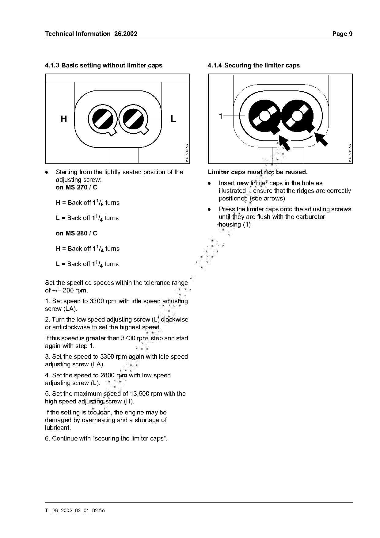
4.1.3 Basic setting without limiter caps                             4.1.4 Securing the limiter caps

     H                                          L                        1

                                                       146TI013 KN

                                                                                                                          146TI014 KN
.   Starting from the lightly seated position of the                 Limiter caps must not be reused.
    adjusting screw:

                                                                     .   Insert new limiter caps in the hole as
    on MS 270 / C
                                                                         illustrated – ensure that the ridges are correctly
                                                                         positioned (see arrows)
    H = Back off 11/8 turns

                                                                     .   Press the limiter caps onto the adjusting screws
    L = Back off 11/4 turns                                              until they are flush with the carburetor

    on MS 280 / C
                                                                         housing (1)
    H = Back off 11/4 turns

    L = Back off 11/4 turns

Set the specified speeds within the tolerance range
of +/– 200 rpm.

1. Set speed to 3300 rpm with idle speed adjusting

screw (LA).
2. Turn the low speed adjusting screw (L) clockwise
or anticlockwise to set the highest speed.

If this speed is greater than 3700 rpm, stop and start
again with step 1.

3. Set the speed to 3300 rpm again with idle speed
adjusting screw (LA).

4. Set the speed to 2800 rpm with low speed
adjusting screw (L).
5. Set the maximum speed of 13,500 rpm with the

high speed adjusting screw (H).
If the setting is too lean, the engine may be
damaged by overheating and a shortage of
lubricant.
6. Continue with "securing the limiter caps".

TI_26_2002_02_01_02.fm
Page 10 of 14
Text of page 10 — search, copy, screen readers
Page 10                                                                                Technical Information 26.2002

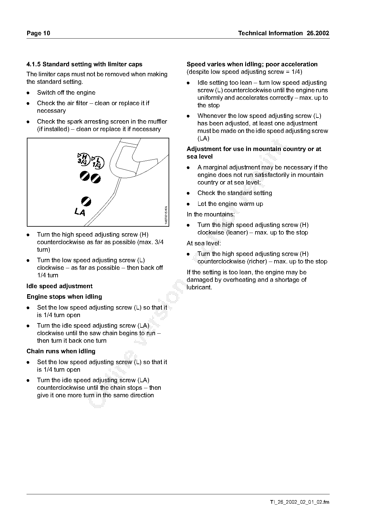
4.1.5 Standard setting with limiter caps                           Speed varies when idling; poor acceleration
The limiter caps must not be removed when making                   (despite low speed adjusting screw = 1/4)
the standard setting.                                              .   Idle setting too lean – turn low speed adjusting
.   Switch off the engine                                              screw (L) counterclockwise until the engine runs
                                                                       uniformly and accelerates correctly – max. up to
.   Check the air filter – clean or replace it if                      the stop
    necessary
                                                                   .   Whenever the low speed adjusting screw (L)
.   Check the spark arresting screen in the muffler                    has been adjusted, at least one adjustment
    (if installed) – clean or replace it if necessary                  must be made on the idle speed adjusting screw
                                                                       (LA)

                                                                   Adjustment for use in mountain country or at

                                                                   sea level
                                                                   .   A marginal adjustment may be necessary if the
                                                                       engine does not run satisfactorily in mountain

                                                                       country or at sea level:
                                                                   .   Check the standard setting

                                                                   .   Let the engine warm up
                                                     146TI015 KN

                  LA                                               In the mountains:
                                                                   .       fo
                                                                       Turn the high speed adjusting screw (H)
                                                                       clockwise (leaner) – max. up to the stop
.   Turn the high speed adjusting screw (H)
    counterclockwise as far as possible (max. 3/4
                                                                   At sea level:
    turn)
                                                                   .   Turn the high speed adjusting screw (H)

.   Turn the low speed adjusting screw (L)                             counterclockwise (richer) – max. up to the stop
    clockwise – as far as possible – then back off
                                                                   If the setting is too lean, the engine may be
    1/4 turn
                                                                   damaged by overheating and a shortage of
Idle speed adjustment                                              lubricant.

Engine stops when idling

.   Set the low speed adjusting screw (L) so that it
    is 1/4 turn open
.

    Turn the idle speed adjusting screw (LA)
    clockwise until the saw chain begins to run –
    then turn it back one turn

Chain runs when idling
.   Set the low speed adjusting screw (L) so that it

    is 1/4 turn open
.   Turn the idle speed adjusting screw (LA)
    counterclockwise until the chain stops – then

    give it one more turn in the same direction

                                                                                                  TI_26_2002_02_01_02.fm
Page 11 of 14
Text of page 11 — search, copy, screen readers
Technical Information 26.2002                                                                                         Page 11

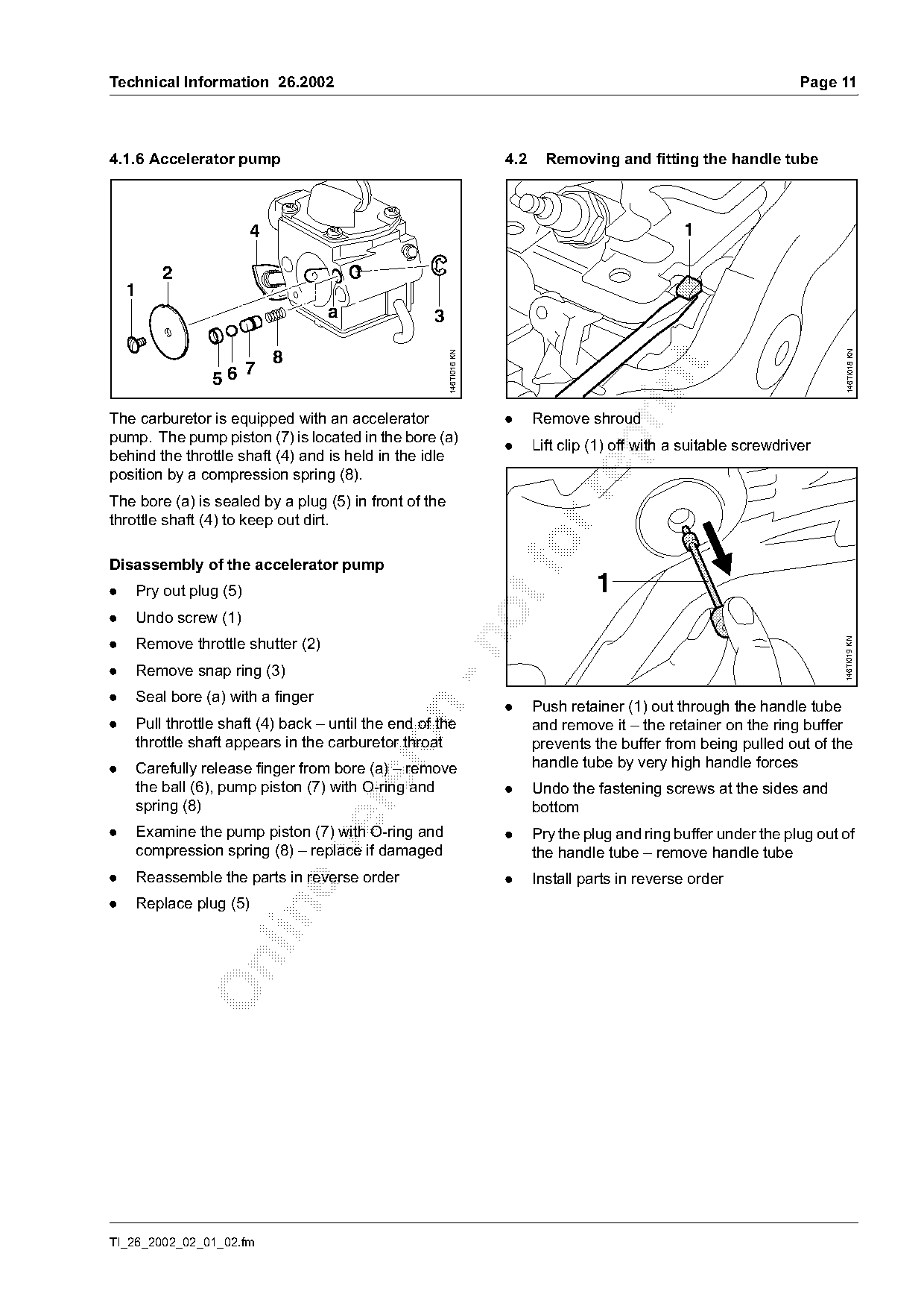
4.1.6 Accelerator pump                                               4.2     Removing and fitting the handle tube

                       4                                                                           1

        2
    1
                                  a                3

                                                                                                                           146TI018 KN
                                                       146TI016 KN
                           8

                       7
                56

The carburetor is equipped with an accelerator                       .     Remove shroud
pump. The pump piston (7) is located in the bore (a)

                                                                     .     Lift clip (1) off with a suitable screwdriver
behind the throttle shaft (4) and is held in the idle
position by a compression spring (8).

The bore (a) is sealed by a plug (5) in front of the
throttle shaft (4) to keep out dirt.

Disassembly of the accelerator pump
.   Pry out plug (5)                                                                 1
.   Undo screw (1)

.   Remove throttle shutter (2)

                                                                                                                           146TI019 KN
.   Remove snap ring (3)
.   Seal bore (a) with a finger
                                                                     .     Push retainer (1) out through the handle tube

.   Pull throttle shaft (4) back – until the end of the                    and remove it – the retainer on the ring buffer

    throttle shaft appears in the carburetor throat                        prevents the buffer from being pulled out of the
.   Carefully release finger from bore (a) – remove                        handle tube by very high handle forces
    the ball (6), pump piston (7) with O-ring and                    .     Undo the fastening screws at the sides and

    spring (8)                                                             bottom
.   Examine the pump piston (7) with O-ring and                      .     Pry the plug and ring buffer under the plug out of

    compression spring (8) – replace if damaged                            the handle tube – remove handle tube
.   Reassemble the parts in reverse order                            .     Install parts in reverse order
.   Replace plug (5)

TI_26_2002_02_01_02.fm
Page 12 of 14
Text of page 12 — search, copy, screen readers
Page 12                                                                        Technical Information 26.2002

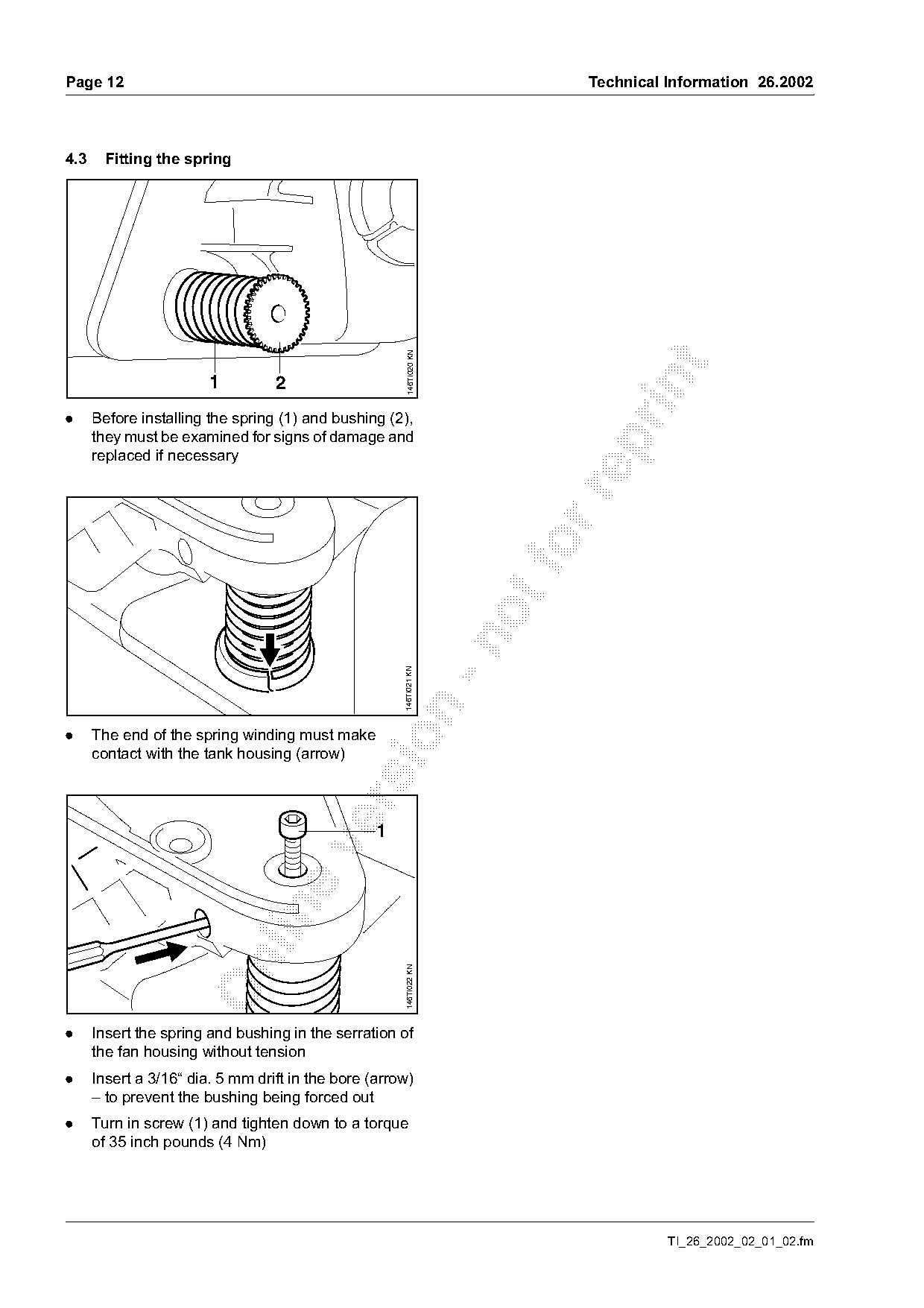
4.3     Fitting the spring

                                                       146TI020 KN

                        1         2
.     Before installing the spring (1) and bushing (2),
      they must be examined for signs of damage and

      replaced if necessary

                                                      146TI021 KN

.     The end of the spring winding must make

      contact with the tank housing (arrow)


                                                      146TI022 KN

.     Insert the spring and bushing in the serration of
      the fan housing without tension
.     Insert a 3/16“ dia. 5 mm drift in the bore (arrow)
      – to prevent the bushing being forced out
.     Turn in screw (1) and tighten down to a torque
      of 35 inch pounds (4 Nm)

                                                                                         TI_26_2002_02_01_02.fm
Page 13 of 14
Text of page 13 — search, copy, screen readers
Technical Information 26.2002                                                                          Page 13

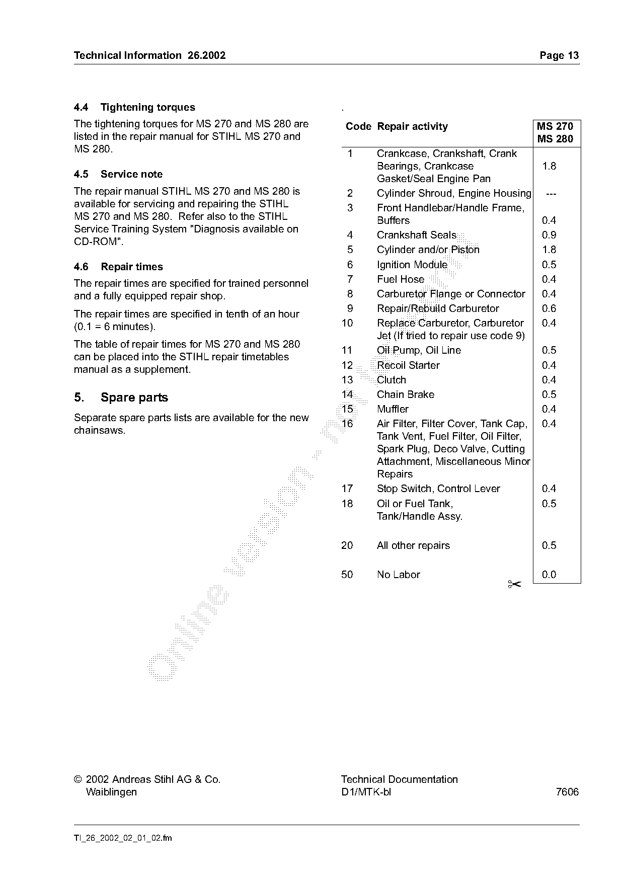
4.4   Tightening torques                               .
The tightening torques for MS 270 and MS 280 are           Code Repair activity                        MS 270
listed in the repair manual for STIHL MS 270 and                                                       MS 280
MS 280.                                                    1     Crankcase, Crankshaft, Crank
                                                                 Bearings, Crankcase                   1.8
4.5   Service note                                               Gasket/Seal Engine Pan
The repair manual STIHL MS 270 and MS 280 is               2     Cylinder Shroud, Engine Housing        ---
available for servicing and repairing the STIHL            3     Front Handlebar/Handle Frame,
MS 270 and MS 280. Refer also to the STIHL                       Buffers                               0.4
Service Training System "Diagnosis available on
                                                        4        Crankshaft Seals                      0.9
CD-ROM".

                                                        5        Cylinder and/or Piston                1.8

4.6   Repair times                                      6        Ignition Module                       0.5
The repair times are specified for trained personnel    7        Fuel Hose                             0.4
and a fully equipped repair shop.                       8        Carburetor Flange or Connector        0.4

                                                        9        Repair/Rebuild Carburetor             0.6
The repair times are specified in tenth of an hour
(0.1 = 6 minutes).                                     10        Replace Carburetor, Carburetor        0.4

                                                                 Jet (If tried to repair use code 9)
The table of repair times for MS 270 and MS 280
                                                       11        Oil Pump, Oil Line                    0.5
can be placed into the STIHL repair timetables
                                                       12        Recoil Starter                        0.4
manual as a supplement.
                                                       13
                                                           fo    Clutch                                0.4
5.    Spare parts                                      14        Chain Brake                           0.5
                                                       15        Muffler                               0.4
Separate spare parts lists are available for the new
                                                       16        Air Filter, Filter Cover, Tank Cap,   0.4
chainsaws.

                                                                 Tank Vent, Fuel Filter, Oil Filter,
                                                                 Spark Plug, Deco Valve, Cutting
                                                                 Attachment, Miscellaneous Minor
                                                                 Repairs

                                                       17        Stop Switch, Control Lever            0.4

                                                       18        Oil or Fuel Tank,                     0.5
                                                                 Tank/Handle Assy.

                                                       20        All other repairs                     0.5

                                                       50        No Labor                              0.0
                                                                                              ✂

© 2002 Andreas Stihl AG & Co.                          Technical Documentation
  Waiblingen                                           D1/MTK-bl                                          7606

TI_26_2002_02_01_02.fm
Page 14 of 14

Text of page 14 — search, copy, screen readers
Page 14                         Technical Information 26.2002

                                          TI_26_2002_02_01_02.fm
Most of these PDFs embed fonts with a shifted character map, so the text above was recovered rather than copied — read it as a faithful but imperfect transcription, and treat the page image above each block as the authority where the two disagree — the figures exist only there, because they are vector drawings that text extraction cannot keep.