Technical Information · issue 21 of 2005
Limiter cap; Segment; Spare parts; Removal of the limiter caps; Summary
Full text
Page 1 of 4
Text of page 1 — search, copy, screen readers
STIH)

Technical Information                                                             21.2005

  Chainsaws STIHL MS 260                                                    – Series 1121
  Chainsaws STIHL MS 270, 280                                               – Series 1133
  Chainsaws STIHL MS 290, 310, 390                                          – Series 1127
  Chainsaws STIHL MS 361                                                    – Series 1135
  Chainsaws STIHL MS 440, 460                                               – Series 1128
  Chainsaws STIHL MS 650, 660                                               – Series 1122
  Blowers STIHL BR 320, 340, 400, 420                                       – Series 4203
  Mistblowers STIHL SR 320, 340, 400, 420                                   – Series 4203
  Clearing saws STIHL FS 550                                                – Series 4116

  Contents
  1.   Limiter cap
  2.   Segment
  3.   Spare parts
  4.   Removal of the limiter caps
  5.   Summary

  Carburetor: limiter cap
  The limiter caps 4203 121 2700 and segment on the
  carburetor have been modified for easier alignment.

  1.      Limiter cap
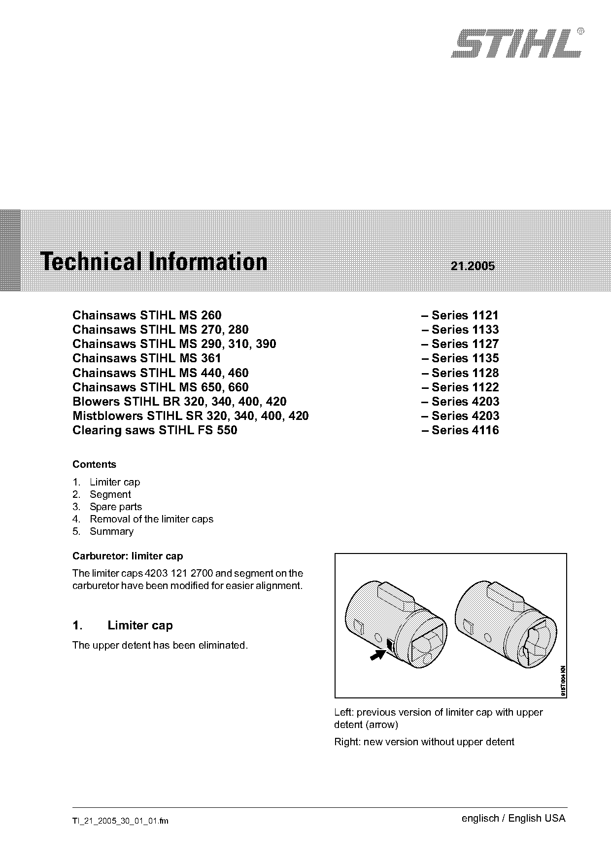
  The upper detent has been eliminated.

                                                        Left: previous version of limiter cap with upper
                                                        detent (arrow)
                                                        Right: new version without upper detent

  TI_21_2005_30_01_01.fm                                                             englisch / English USA
Page 2 of 4
Text of page 2 — search, copy, screen readers
Page 2                                                                         Technical Information 21.2005

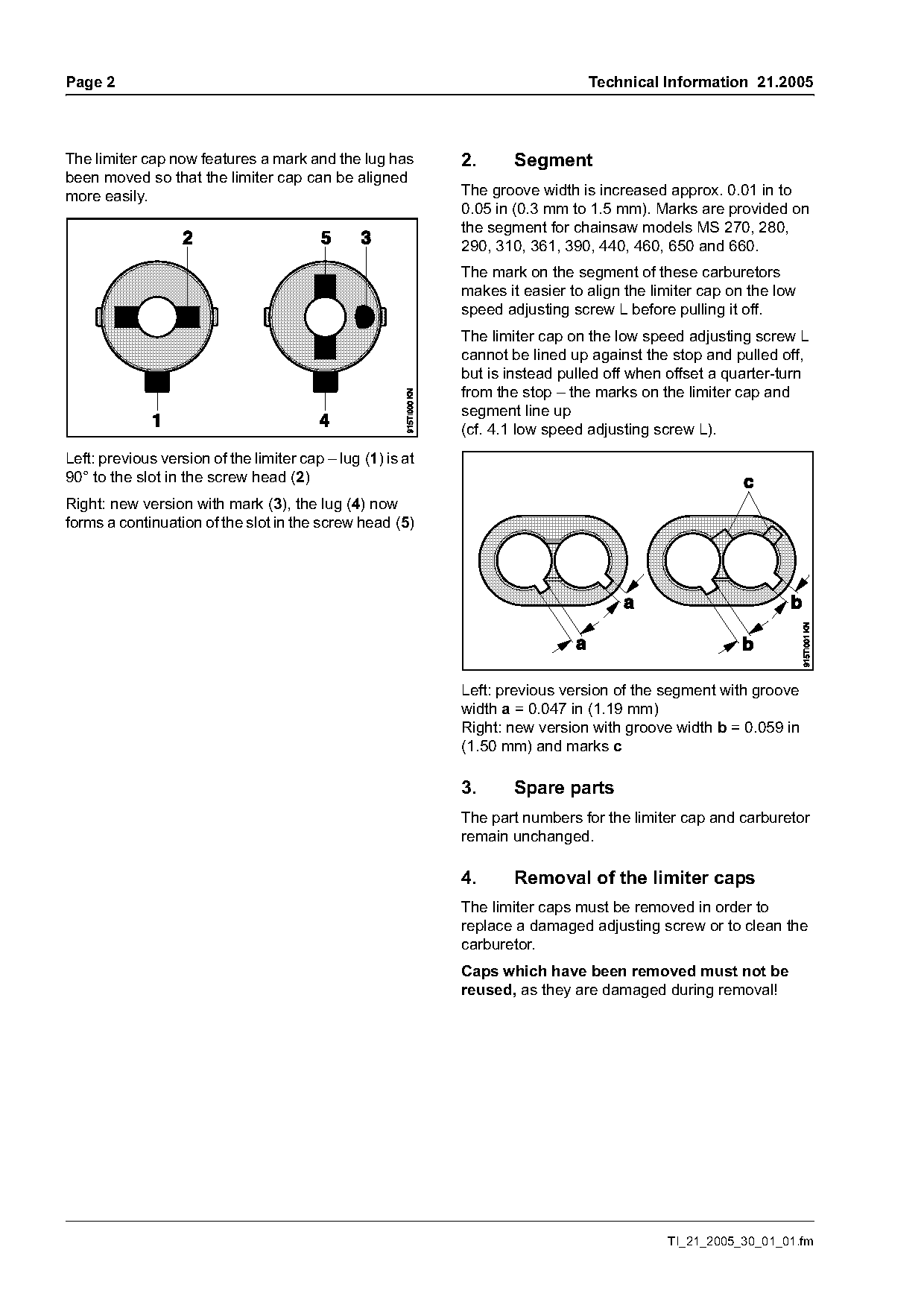
The limiter cap now features a mark and the lug has         2.      Segment
been moved so that the limiter cap can be aligned
more easily.                                                The groove width is increased approx. 0.01 in to
                                                            0.05 in (0.3 mm to 1.5 mm). Marks are provided on
                                                            the segment for chainsaw models MS 270, 280,
                                                            290, 310, 361, 390, 440, 460, 650 and 660.
                                                            The mark on the segment of these carburetors
                                                            makes it easier to align the limiter cap on the low
                                                            speed adjusting screw L before pulling it off.
                                                            The limiter cap on the low speed adjusting screw L
                                                            cannot be lined up against the stop and pulled off,
                                                            but is instead pulled off when offset a quarter-turn
                                                            from the stop – the marks on the limiter cap and
                                                            segment line up
                                                            (cf. 4.1 low speed adjusting screw L).
Left: previous version of the limiter cap – lug (1) is at
90° to the slot in the screw head (2)
Right: new version with mark (3), the lug (4) now
forms a continuation of the slot in the screw head (5)

                                                            Left: previous version of the segment with groove
                                                            width a = 0.047 in (1.19 mm)
                                                            Right: new version with groove width b = 0.059 in
                                                            (1.50 mm) and marks c

                                                            3.      Spare parts
                                                            The part numbers for the limiter cap and carburetor
                                                            remain unchanged.

                                                            4.      Removal of the limiter caps
                                                            The limiter caps must be removed in order to
                                                            replace a damaged adjusting screw or to clean the
                                                            carburetor.
                                                            Caps which have been removed must not be
                                                            reused, as they are damaged during removal!

                                                                                           TI_21_2005_30_01_01.fm
Page 3 of 4
Text of page 3 — search, copy, screen readers
Technical Information 21.2005                                                                           Page 3

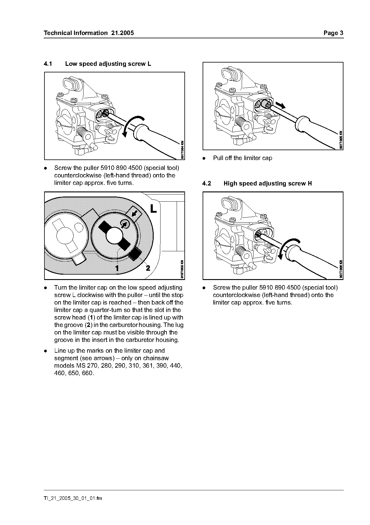
4.1       Low speed adjusting screw L

                                                           .     Pull off the limiter cap
.     Screw the puller 5910 890 4500 (special tool)
      counterclockwise (left-hand thread) onto the
      limiter cap approx. five turns.                      4.2       High speed adjusting screw H

.     Turn the limiter cap on the low speed adjusting      .     Screw the puller 5910 890 4500 (special tool)
      screw L clockwise with the puller – until the stop         counterclockwise (left-hand thread) onto the
      on the limiter cap is reached – then back off the          limiter cap approx. five turns.
      limiter cap a quarter-turn so that the slot in the
      screw head (1) of the limiter cap is lined up with
      the groove (2) in the carburetor housing. The lug
      on the limiter cap must be visible through the
      groove in the insert in the carburetor housing.
.     Line up the marks on the limiter cap and
      segment (see arrows) – only on chainsaw
      models MS 270, 280, 290, 310, 361, 390, 440,
      460, 650, 660.

TI_21_2005_30_01_01.fm
Page 4 of 4
Text of page 4 — search, copy, screen readers
Page 4                                                                               Technical Information 21.2005


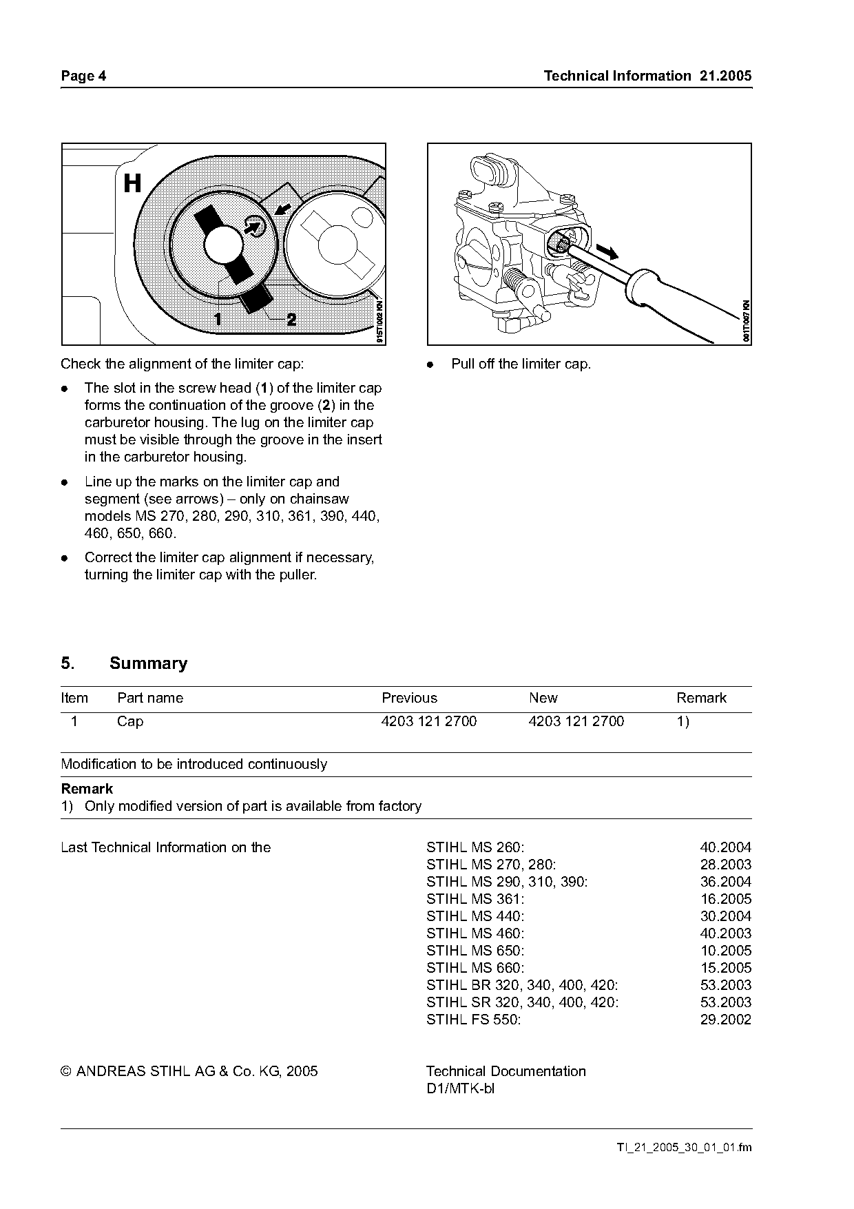
Check the alignment of the limiter cap:                         .    Pull off the limiter cap.
.       The slot in the screw head (1) of the limiter cap
        forms the continuation of the groove (2) in the
        carburetor housing. The lug on the limiter cap
        must be visible through the groove in the insert
        in the carburetor housing.
.       Line up the marks on the limiter cap and
        segment (see arrows) – only on chainsaw
        models MS 270, 280, 290, 310, 361, 390, 440,
        460, 650, 660.
.       Correct the limiter cap alignment if necessary,
        turning the limiter cap with the puller.

5.          Summary
Item         Part name                                    Previous                New                     Remark
    1        Cap                                          4203 121 2700           4203 121 2700           1)

Modification to be introduced continuously
Remark
1) Only modified version of part is available from factory

Last Technical Information on the                               STIHL MS 260:                                  40.2004
                                                                STIHL MS 270, 280:                             28.2003
                                                                STIHL MS 290, 310, 390:                        36.2004
                                                                STIHL MS 361:                                  16.2005
                                                                STIHL MS 440:                                  30.2004
                                                                STIHL MS 460:                                  40.2003
                                                                STIHL MS 650:                                  10.2005
                                                                STIHL MS 660:                                  15.2005
                                                                STIHL BR 320, 340, 400, 420:                   53.2003
                                                                STIHL SR 320, 340, 400, 420:                   53.2003
                                                                STIHL FS 550:                                  29.2002

© ANDREAS STIHL AG & Co. KG, 2005                               Technical Documentation
                                                                D1/MTK-bl

                                                                                                 TI_21_2005_30_01_01.fm
Most of these PDFs embed fonts with a shifted character map, so the text above was recovered rather than copied — read it as a faithful but imperfect transcription, and treat the page image above each block as the authority where the two disagree — the figures exist only there, because they are vector drawings that text extraction cannot keep.