Technical Information · issue 14 of 2006
New chain saws STIHL MS 441, MS 441 C-Q – Series
IssueTI 14/2006
Engine family 1138
Full text
Page 1 of 16
Text of page 1 — search, copy, screen readers
STIH)

Technical Information                                     14.2006

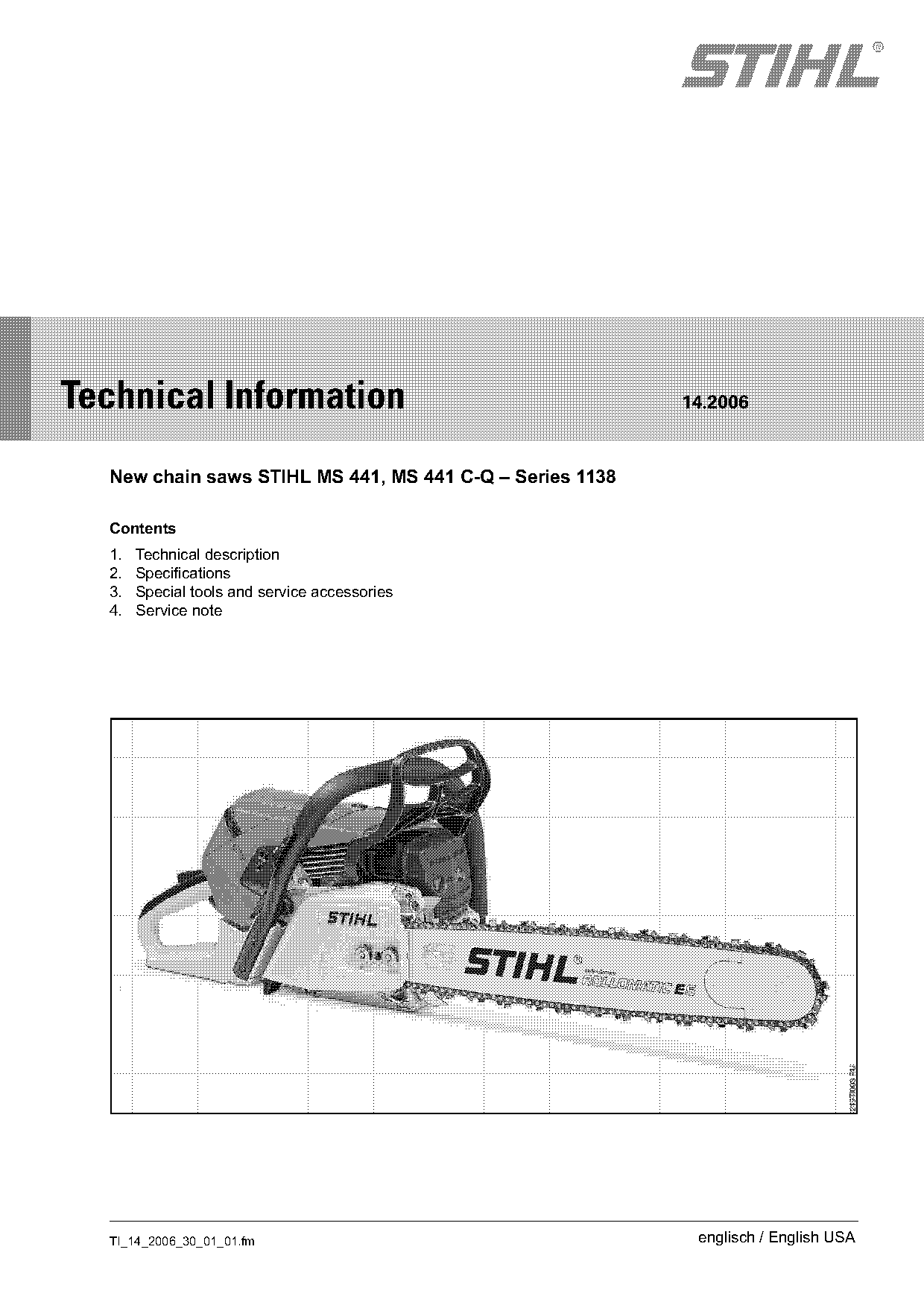
  New chain saws STIHL MS 441, MS 441 C-Q – Series 1138

  Contents
  1.   Technical description
  2.   Specifications
  3.   Special tools and service accessories
  4.   Service note

  TI_14_2006_30_01_01.fm                                   englisch / English USA
Page 2 of 16
Text of page 2 — search, copy, screen readers
Page 2                                                                         Technical Information 14.2006

High performance, low vibrations and light : these       1.        Technical description
are the features characterizing the new professional
chain saw models MS 441 and MS 441 C-Q from              1.1       Principle of operation, stratified
STIHL.                                                             scavenging
The new STIHL two-stroke power unit with four-port       A cushion of air (fuel-free air) separates the fuel-air
technology and stratified scavenging yields:             mixture from the exhaust gas. This cushion of air is
-   high power,                                          located in front of the fuel-air mixture. At the start of
                                                         the exhausting and scavenging cycle, fuel-free air
-   high torque over a wide range of speeds,             first streams from the transfer ports into the
-   distinctly lower fuel consumption – up to 20% as     combustion chamber and scavenges the exhaust
    compared with conventional two-stroke engines        gas into the exhaust port. The air prevents the
                                                         subsequent fuel-air mixture from entering the
The MS 441 and MS 441 C-Q are designed and
                                                         exhaust port, thus reducing the fuel-laden
built for a wide variety of uses in timber harvesting
                                                         scavenging losses and the fuel consumption.
and general timber work.
The air filter system with pre-separation distinctly
extends the intervals between cleaning (filter life is   1.1.1      Mechanical design
roughly doubled in comparison to the MS 440).
The newly designed anti-vibration system provides
low vibrations.
The ignition system with electronic adjustment of the
ignition timing permits optimum performance, as
well as reducing exhaust emissions.
ElastoStart™ plus (i.e. ElastoStart™ starter handle
and decompression valve) allows convenient                     4
starting.
The MS 441 is optionally available with heated                 1
handles and carburetor heating.
The MS 441 C-Q additionally features a dual chain              2
brake system.

                                                                                                                000TI043 KN
                                                                                             3

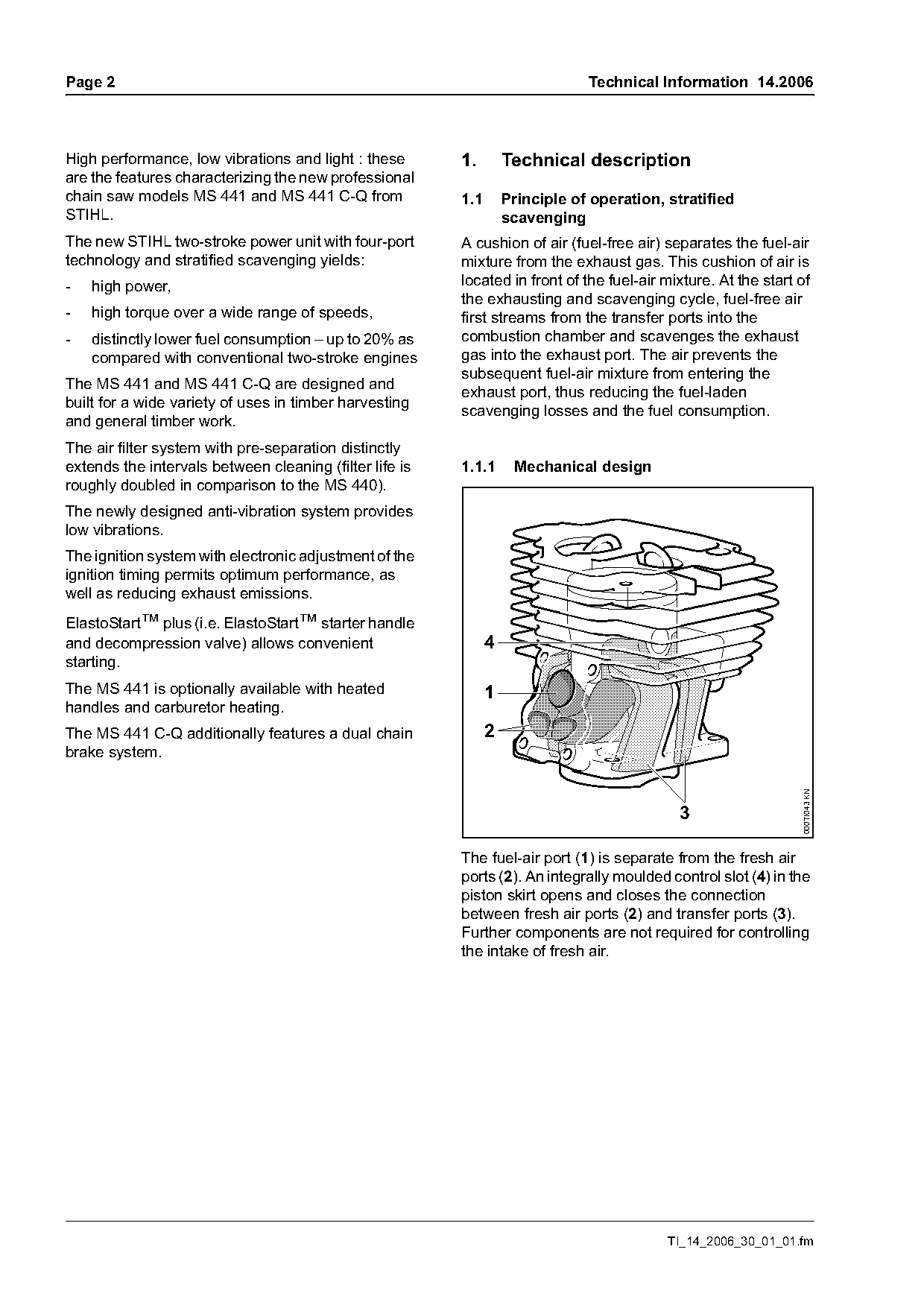
                                                         The fuel-air port (1) is separate from the fresh air
                                                         ports (2). An integrally moulded control slot (4) in the
                                                         piston skirt opens and closes the connection
                                                         between fresh air ports (2) and transfer ports (3).
                                                         Further components are not required for controlling
                                                         the intake of fresh air.

                                                                                           TI_14_2006_30_01_01.fm
Page 3 of 16
Text of page 3 — search, copy, screen readers
Technical Information 14.2006                                                                                   Page 3

1.1.2    Compression and intake

        1
        2                                                                              1
                                                                   2                                        2
                                                                   3                                        3

                                                                                                                     000TI044 KN
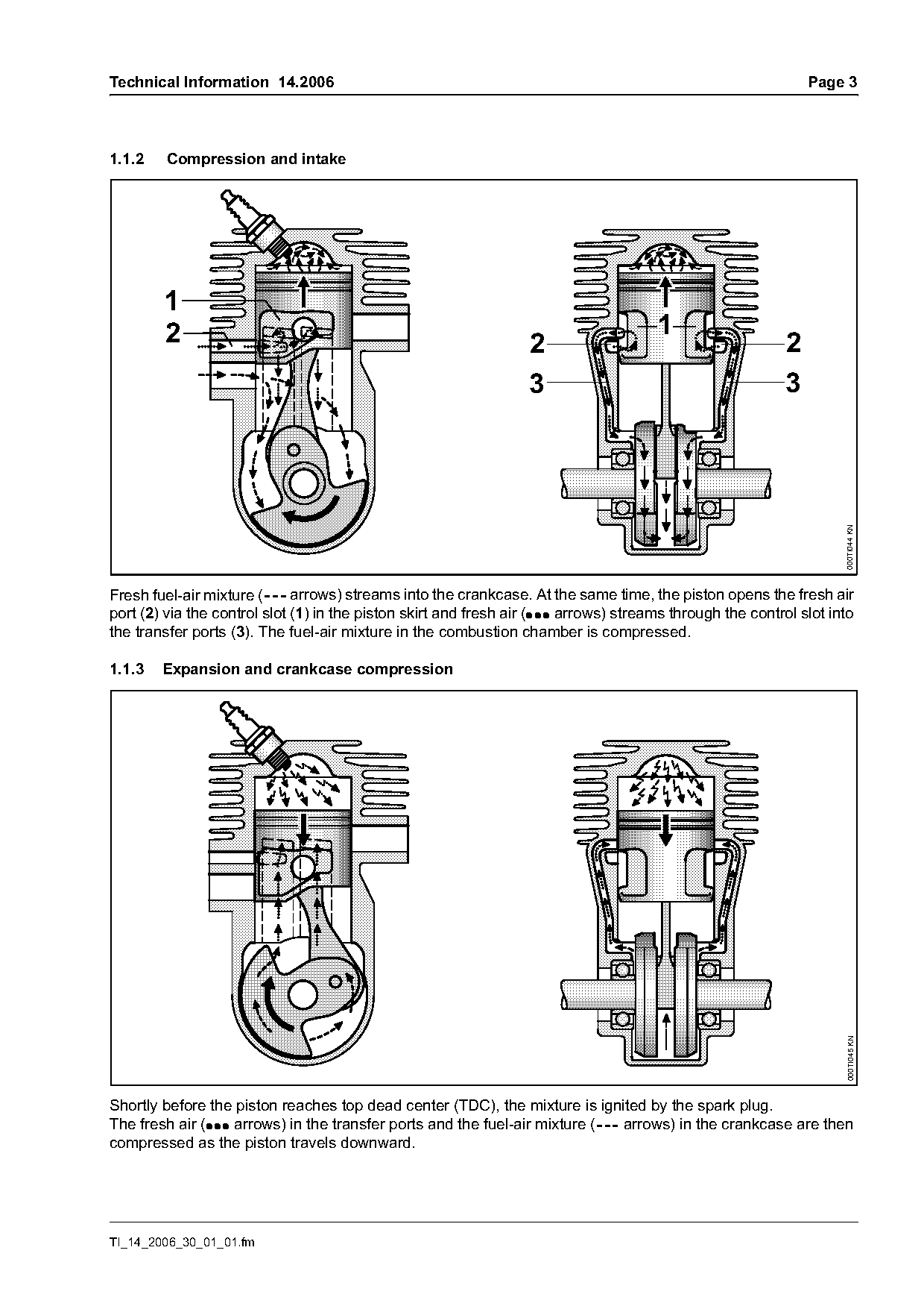
Fresh fuel-air mixture (--- arrows) streams into the crankcase. At the same time, the piston opens the fresh air
port (2) via the control slot (1) in the piston skirt and fresh air (: :: arrows) streams through the control slot into
the transfer ports (3). The fuel-air mixture in the combustion chamber is compressed.

1.1.3   Expansion and crankcase compression

                                                                                                                     000TI045 KN

Shortly before the piston reaches top dead center (TDC), the mixture is ignited by the spark plug.
The fresh air (::: arrows) in the transfer ports and the fuel-air mixture (--- arrows) in the crankcase are then
compressed as the piston travels downward.

TI_14_2006_30_01_01.fm
Page 4 of 16
Text of page 4 — search, copy, screen readers
Page 4                                                                     Technical Information 14.2006

1.1.4    Exhausting and scavenging

                                                                                                          000TI046 KN
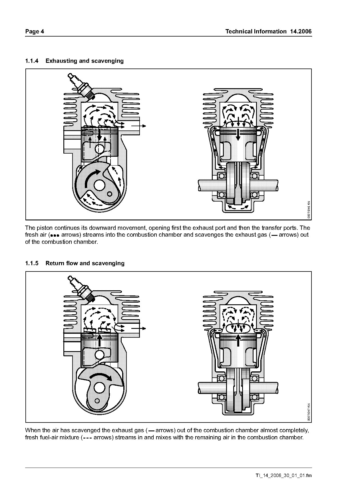
The piston continues its downward movement, opening first the exhaust port and then the transfer ports. The
fresh air (:: : arrows) streams into the combustion chamber and scavenges the exhaust gas (--- arrows) out
of the combustion chamber.

1.1.5    Return flow and scavenging

                                                                                                          000TI047 KN

When the air has scavenged the exhaust gas (--- arrows) out of the combustion chamber almost completely,
fresh fuel-air mixture (--- arrows) streams in and mixes with the remaining air in the combustion chamber.

                                                                                      TI_14_2006_30_01_01.fm
Page 5 of 16
Text of page 5 — search, copy, screen readers
Technical Information 14.2006                                                                           Page 5

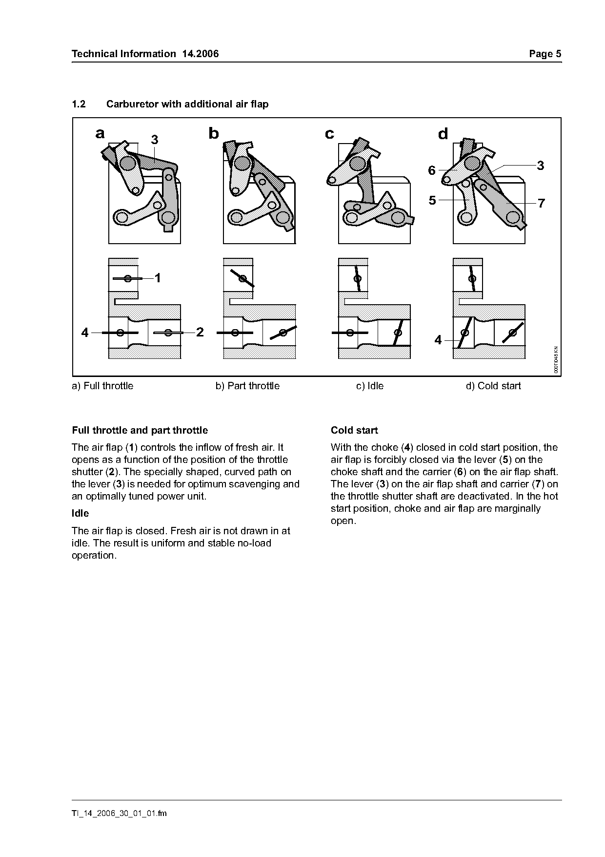
1.2        Carburetor with additional air flap

       a            3             b                     c                          d

                                                                              6                          3

                                                                               5                         7


  4                           2
                                                                                4

                                                                                                             000TI048 KN
a) Full throttle                  b) Part throttle            c) Idle                   d) Cold start

Full throttle and part throttle                         Cold start
The air flap (1) controls the inflow of fresh air. It   With the choke (4) closed in cold start position, the
opens as a function of the position of the throttle     air flap is forcibly closed via the lever (5) on the
shutter (2). The specially shaped, curved path on       choke shaft and the carrier (6) on the air flap shaft.
the lever (3) is needed for optimum scavenging and      The lever (3) on the air flap shaft and carrier (7) on
an optimally tuned power unit.                          the throttle shutter shaft are deactivated. In the hot
                                                        start position, choke and air flap are marginally
Idle
                                                        open.
The air flap is closed. Fresh air is not drawn in at
idle. The result is uniform and stable no-load
operation.

TI_14_2006_30_01_01.fm
Page 6 of 16
Text of page 6 — search, copy, screen readers
Page 6                                                                               Technical Information 14.2006

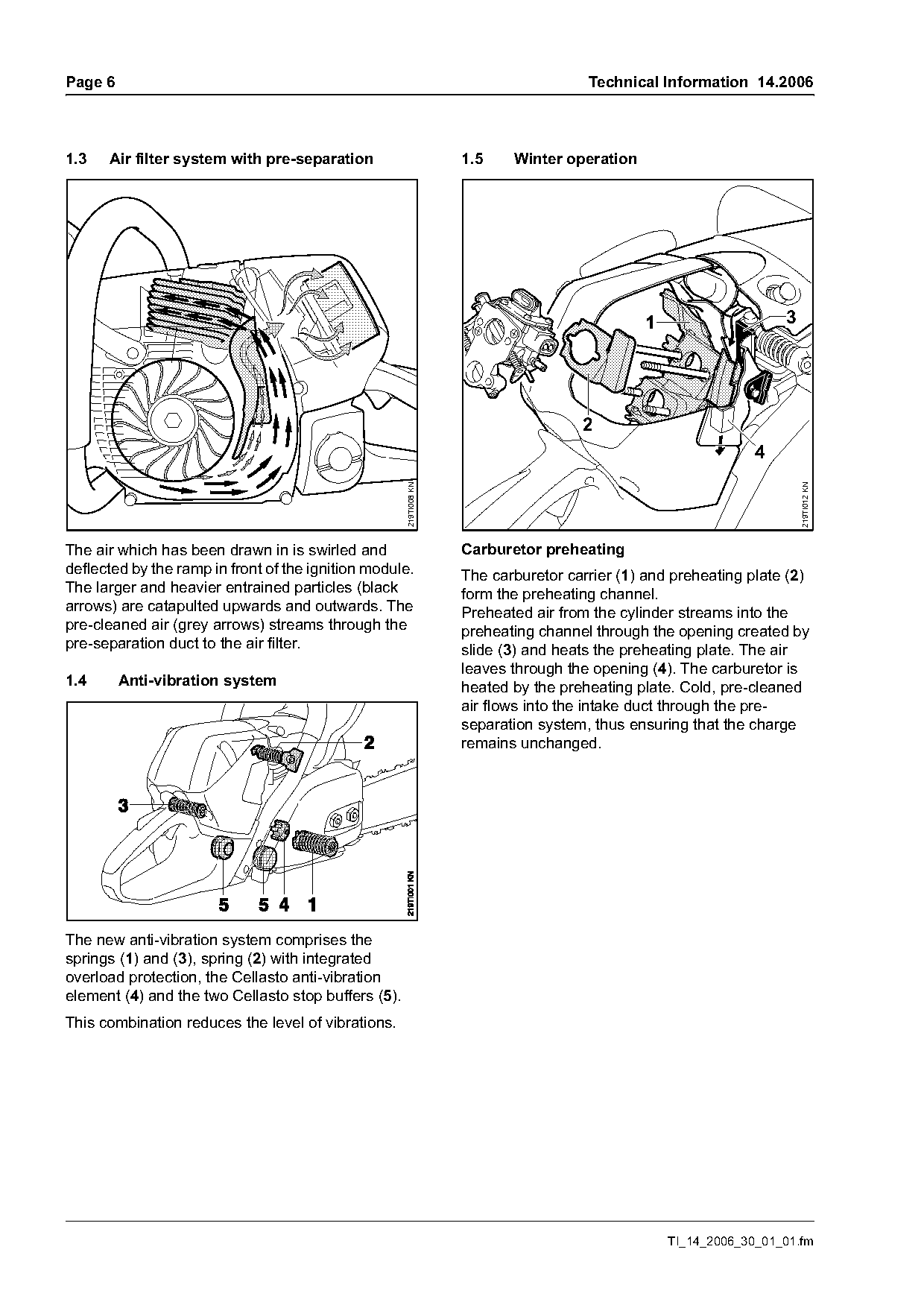
1.3   Air filter system with pre-separation                        1.5    Winter operation

                                                                                             1                    3

                                                                                    2
                                                                                                              4
                                                     219TI008 KN

                                                                                                                      219TI012 KN
The air which has been drawn in is swirled and                     Carburetor preheating
deflected by the ramp in front of the ignition module.             The carburetor carrier (1) and preheating plate (2)
The larger and heavier entrained particles (black                  form the preheating channel.
arrows) are catapulted upwards and outwards. The                   Preheated air from the cylinder streams into the
pre-cleaned air (grey arrows) streams through the                  preheating channel through the opening created by
pre-separation duct to the air filter.                             slide (3) and heats the preheating plate. The air
                                                                   leaves through the opening (4). The carburetor is
1.4      Anti-vibration system                                     heated by the preheating plate. Cold, pre-cleaned
                                                                   air flows into the intake duct through the pre-
                                                                   separation system, thus ensuring that the charge
                                                                   remains unchanged.

The new anti-vibration system comprises the
springs (1) and (3), spring (2) with integrated
overload protection, the Cellasto anti-vibration
element (4) and the two Cellasto stop buffers (5).
This combination reduces the level of vibrations.

                                                                                                 TI_14_2006_30_01_01.fm
Page 7 of 16
Text of page 7 — search, copy, screen readers
Technical Information 14.2006                                                                              Page 7

1.6       Filler cap                                       2.     Specifications
The filler cap can be opened and closed quickly and
easily:                                                    2.1    Power unit
Large, readily accessible tank openings allow the          STIHL single-cylinder two-stroke engine
machine to be refuelled easily.
                                                           Displacement                4.31 cu in. (70.7 cm3)
1.7       Dual chain brake system (MS 441 C-Q)             Bore                        1.97 in. (50 mm)
                                                           Stroke                      1.41 in. (36 mm)
With this system, the chain sprocket is blocked
when in idle position.                                     Power output to             5.5 hp (4.1 kW)
The throttle trigger interlock simultaneously serves       ISO 7293                    at 9,500 rpm
as actuating lever for the chain brake system. The         Idle speed                  2,800 rpm
brake band releases the clutch drum when the               Permissible maximum
throttle trigger interlock is pressed.                     speed with guide bar and
                                                           chain                       13,500 rpm
When the interlock is released, the brake band
clamps the clutch drum.                                    Weight without guide bar
                                                           and chain
The chain brake can be triggered in three ways:            MS 441                      14.5 lb (6,60 kg )
-     Automatically, by the inertia of the hand guard in   MS 441 with heated
      the presence of a sufficiently strong kickback.      handles                     14.7 lb (6,70 kg)
                                                           MS 441 C-Q                  14.7 lb (6,70 kg)
-     Manually, by pushing the front hand guard
      towards the bar nose.
-     Manually, by releasing the throttle trigger and
                                                           2.2    Ignition system
      throttle interlock.
                                                           Ignition module            Electronically controlled
                                                                                      with automatic ignition
                                                                                      timing adjustment
                                                           Spark plug
                                                           (suppressed)               NGK BPMR 7 A
                                                           Electrode gap              0.020“ (0.5 mm)

TI_14_2006_30_01_01.fm
Page 8 of 16
Text of page 8 — search, copy, screen readers
Page 8                                                                    Technical Information 14.2006

2.3      Fuel system                                 2.4     Chain lubrication
Carburetor                                           Oil pump:                  Speed-dependent pump
All-position diaphragm carburetor                                               with rotary piston –
                                                                                additional manual oil flow
Standard setting with limiter caps                                              control
                                                     Oil tank capacity:         0.76 US pt (0.360 litres)
Low speed adjusting      1/4 turn open
screw L                  (max. up to the stop)
                                                     2.5     Bar and chain
High speed adjusting     3/4 turn open               Guide bar:                 Rollomatic, Duromatic
screw H                  (max. up to the stop)       Oilomatic chains:          Rapid Micro 2,
                                                                                Rapid Micro,
                                                                                Rapid Super,
Basic setting without limiter caps
                                                                                Rapid Super C,
(during repairs)
                                                                                Rapid Super C3
Low speed adjusting                                  Chain pitch:               3/8"
screw L                  1 turn open                 Chain sprocket:            7 teeth for 3/8"
                                                                                (rim sprocket)
High speed adjusting                                                            8 teeth for 3/8" (optional)
screw H                  1 turn open                                            (rim sprocket)

Fuel mixture
See owner's manual.
Fuel tank capacity:      1.53 US pt (0.725 litres)

                                                                                     TI_14_2006_30_01_01.fm
Page 9 of 16
Text of page 9 — search, copy, screen readers
Technical Information 14.2006                                                                                 Page 9

3.      Special tools and service
        accessories

3.1     Special tools
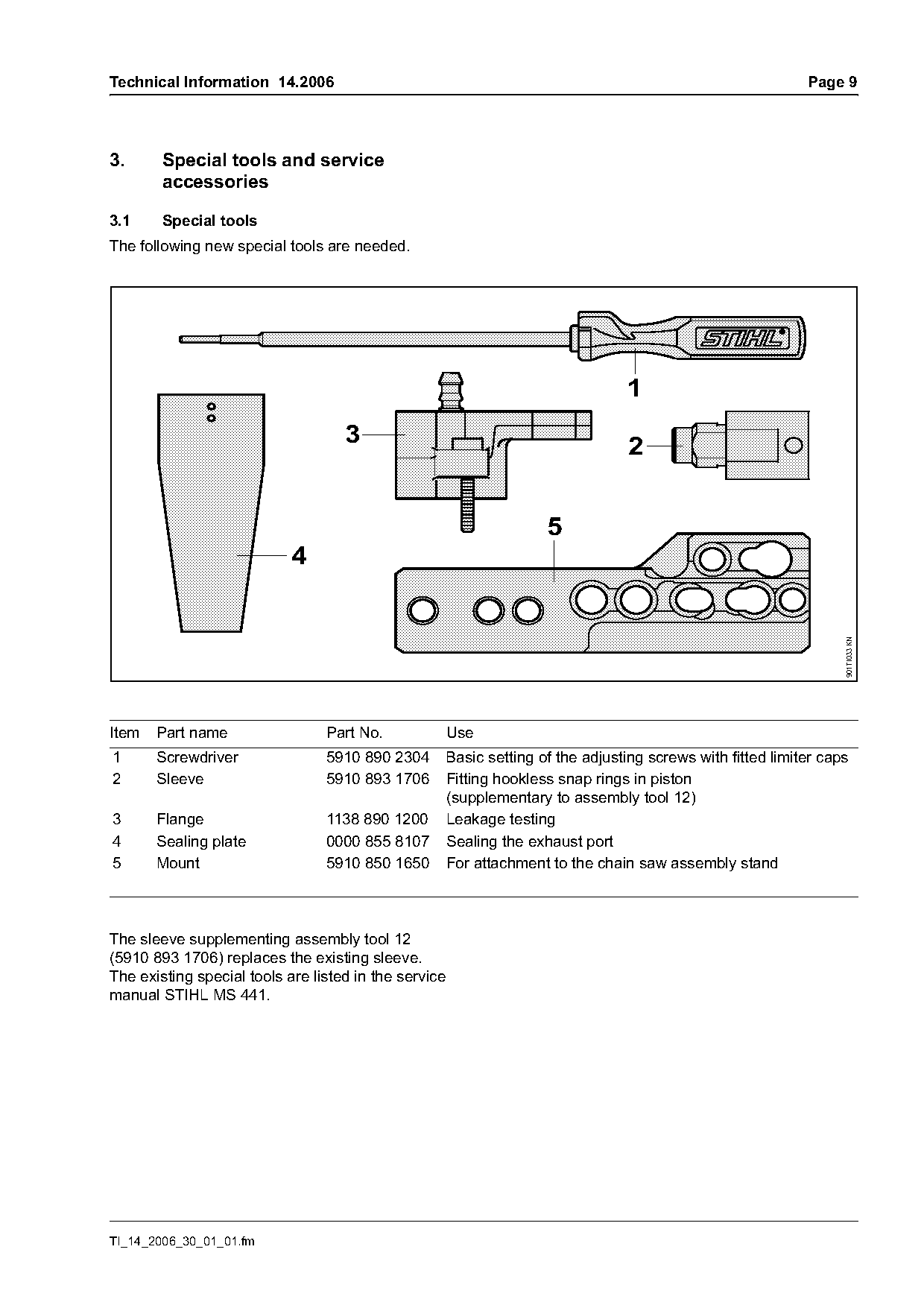
The following new special tools are needed.

                                                                                  1
                                    3                                              2

                                                                      5
                            4

                                                                                                                    901TI033 KN
Item   Part name                 Part No.              Use
1      Screwdriver               5910 890 2304         Basic setting of the adjusting screws with fitted limiter caps
2      Sleeve                    5910 893 1706         Fitting hookless snap rings in piston
                                                       (supplementary to assembly tool 12)
3      Flange                    1138 890 1200         Leakage testing
4      Sealing plate             0000 855 8107         Sealing the exhaust port
5      Mount                     5910 850 1650         For attachment to the chain saw assembly stand

The sleeve supplementing assembly tool 12
(5910 893 1706) replaces the existing sleeve.
The existing special tools are listed in the service
manual STIHL MS 441.

TI_14_2006_30_01_01.fm
Page 10 of 16
Text of page 10 — search, copy, screen readers
Page 10                                                                        Technical Information 14.2006

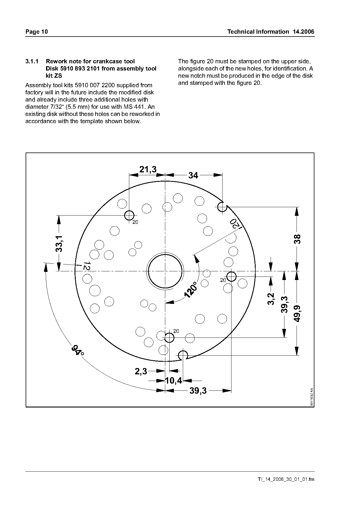
3.1.1   Rework note for crankcase tool                    The figure 20 must be stamped on the upper side,
        Disk 5910 893 2101 from assembly tool             alongside each of the new holes, for identification. A
        kit ZS                                            new notch must be produced in the edge of the disk
Assembly tool kits 5910 007 2200 supplied from            and stamped with the figure 20.
factory will in the future include the modified disk
and already include three additional holes with
diameter 7/32“ (5.5 mm) for use with MS 441. An
existing disk without these holes can be reworked in
accordance with the template shown below.

                                              21,3
                                                              34

                                                                                20
                                         20

                                                                                                       38
          33,1


                                                                          20
                                                                                            3,2
                                                                                                    39,3
                                                                                                  49,9


                                          2,3
                                                       10,4
                                                              39,3
                                                                                                              901TI032 KN

                                                                                         TI_14_2006_30_01_01.fm
Page 11 of 16
Text of page 11 — search, copy, screen readers
Technical Information 14.2006                                                                              Page 11

3.1.2   Rework note for crankcase tool
        Assembly tool AS 5910 890 2205
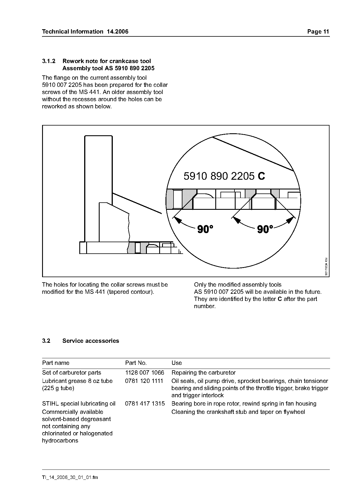
The flange on the current assembly tool
5910 007 2205 has been prepared for the collar
screws of the MS 441. An older assembly tool
without the recesses around the holes can be
reworked as shown below.

                                                         5910 890 2205 C

                                                                                                                  901TI034 KN
The holes for locating the collar screws must be            Only the modified assembly tools
modified for the MS 441 (tapered contour).                  AS 5910 007 2205 will be available in the future.
                                                            They are identified by the letter C after the part
                                                            number.

3.2     Service accessories

Part name                       Part No.           Use
Set of carburetor parts         1128 007 1066      Repairing the carburetor
Lubricant grease 8 oz tube      0781 120 1111      Oil seals, oil pump drive, sprocket bearings, chain tensioner
(225 g tube)                                       bearing and sliding points of the throttle trigger, brake trigger
                                                   and trigger interlock
STIHL special lubricating oil   0781 417 1315      Bearing bore in rope rotor, rewind spring in fan housing
Commercially available                             Cleaning the crankshaft stub and taper on flywheel
solvent-based degreasant
not containing any
chlorinated or halogenated
hydrocarbons

TI_14_2006_30_01_01.fm
Page 12 of 16
Text of page 12 — search, copy, screen readers
Page 12                                                                       Technical Information 14.2006

3.3     Special accessories for the user

Part name                       Part No.           Use
Cover plate kit                 1138 007 1000      In extreme winter conditions (temperatures below 15 ° F or
                                                   -10 °C, powdery or drifting snow) – prevents powdery or
                                                   drifting snow from entering the machine

4.      Service note                                       4.1.2 Basic setting without limiter caps

Specific national safety regulations and the safety
instructions in the owner's manual must be
observed if the chain saw has to be started up
during repairs.

4.1     Carburetor
                                                                   H                                         L
With this carburetor, the user can only adjust the
high speed screw H and low speed screw L within a
range of 258° (approx. 3/4 turn). This ensures that

                                                                                                                  146TI013 KN
the engine always operates at the best possible
setting for full throttle, part throttle and idle.
However, precision adjustments can still be made if
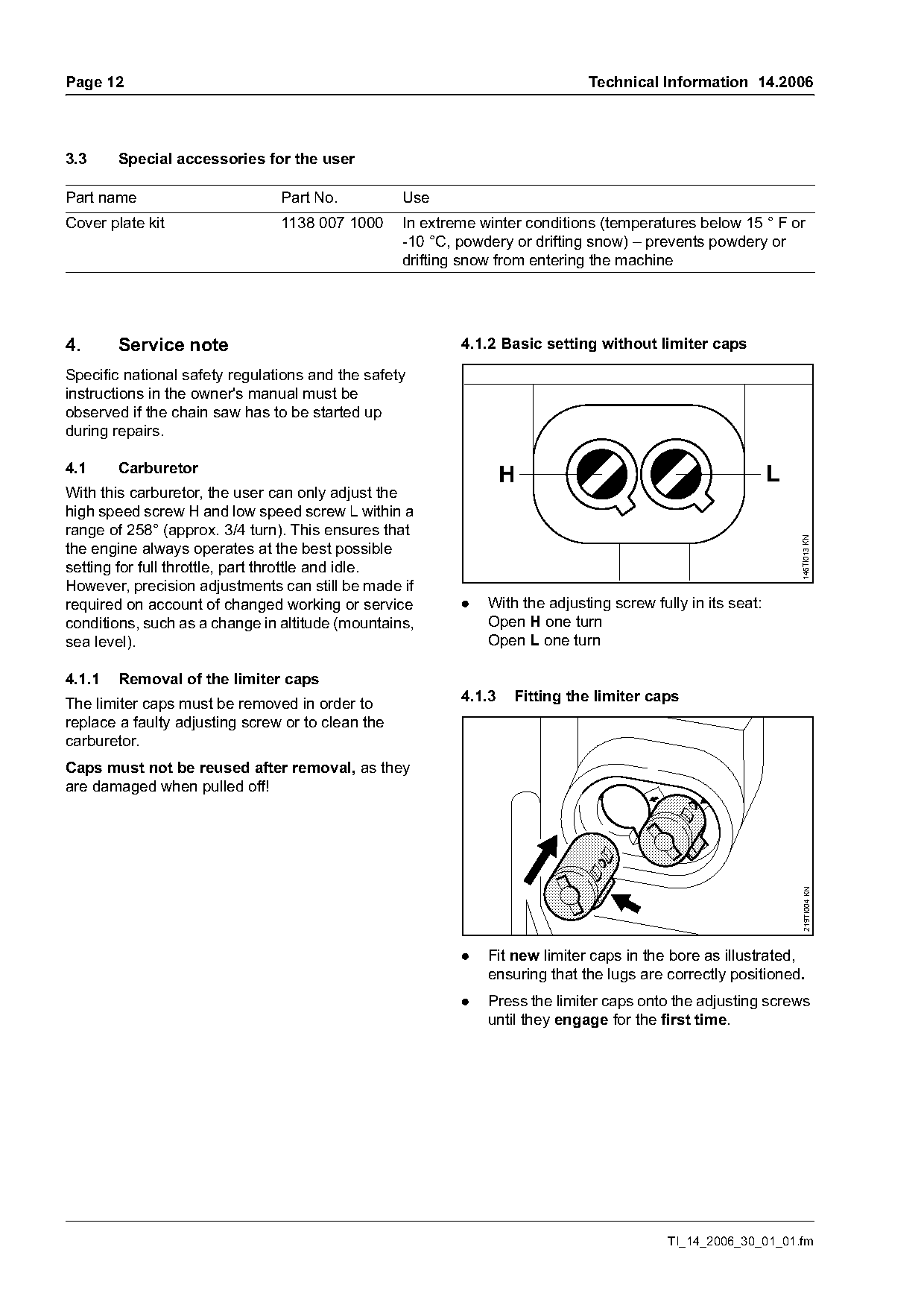
required on account of changed working or service          .   With the adjusting screw fully in its seat:
conditions, such as a change in altitude (mountains,           Open H one turn
sea level).                                                    Open L one turn

4.1.1   Removal of the limiter caps
The limiter caps must be removed in order to               4.1.3   Fitting the limiter caps
replace a faulty adjusting screw or to clean the
carburetor.
Caps must not be reused after removal, as they
are damaged when pulled off!
                                                                                                                 219TI004 KN

                                                           .   Fit new limiter caps in the bore as illustrated,
                                                               ensuring that the lugs are correctly positioned.
                                                           .   Press the limiter caps onto the adjusting screws
                                                               until they engage for the first time.

                                                                                           TI_14_2006_30_01_01.fm
Page 13 of 16
Text of page 13 — search, copy, screen readers
Technical Information 14.2006                                                                                  Page 13

.    Install the carburetor and continue with "Basic                 4.1.5   Securing the limiter caps
     setting with fitted limiter caps".

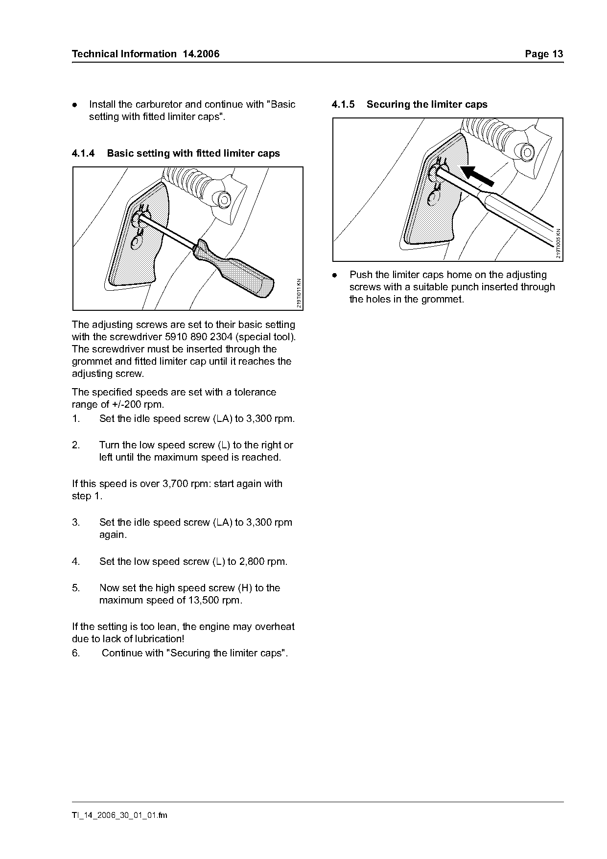
4.1.4    Basic setting with fitted limiter caps

                                                                                                                     219TI005 KN
                                                                     .   Push the limiter caps home on the adjusting

                                                       219TI011 KN
                                                                         screws with a suitable punch inserted through
                                                                         the holes in the grommet.

The adjusting screws are set to their basic setting
with the screwdriver 5910 890 2304 (special tool).
The screwdriver must be inserted through the
grommet and fitted limiter cap until it reaches the
adjusting screw.
The specified speeds are set with a tolerance
range of +/-200 rpm.
1.   Set the idle speed screw (LA) to 3,300 rpm.

2.      Turn the low speed screw (L) to the right or
        left until the maximum speed is reached.

If this speed is over 3,700 rpm: start again with
step 1.

3.      Set the idle speed screw (LA) to 3,300 rpm
        again.

4.      Set the low speed screw (L) to 2,800 rpm.

5.      Now set the high speed screw (H) to the
        maximum speed of 13,500 rpm.

If the setting is too lean, the engine may overheat
due to lack of lubrication!
6.      Continue with "Securing the limiter caps".

TI_14_2006_30_01_01.fm
Page 14 of 16
Text of page 14 — search, copy, screen readers
Page 14                                                                                Technical Information 14.2006

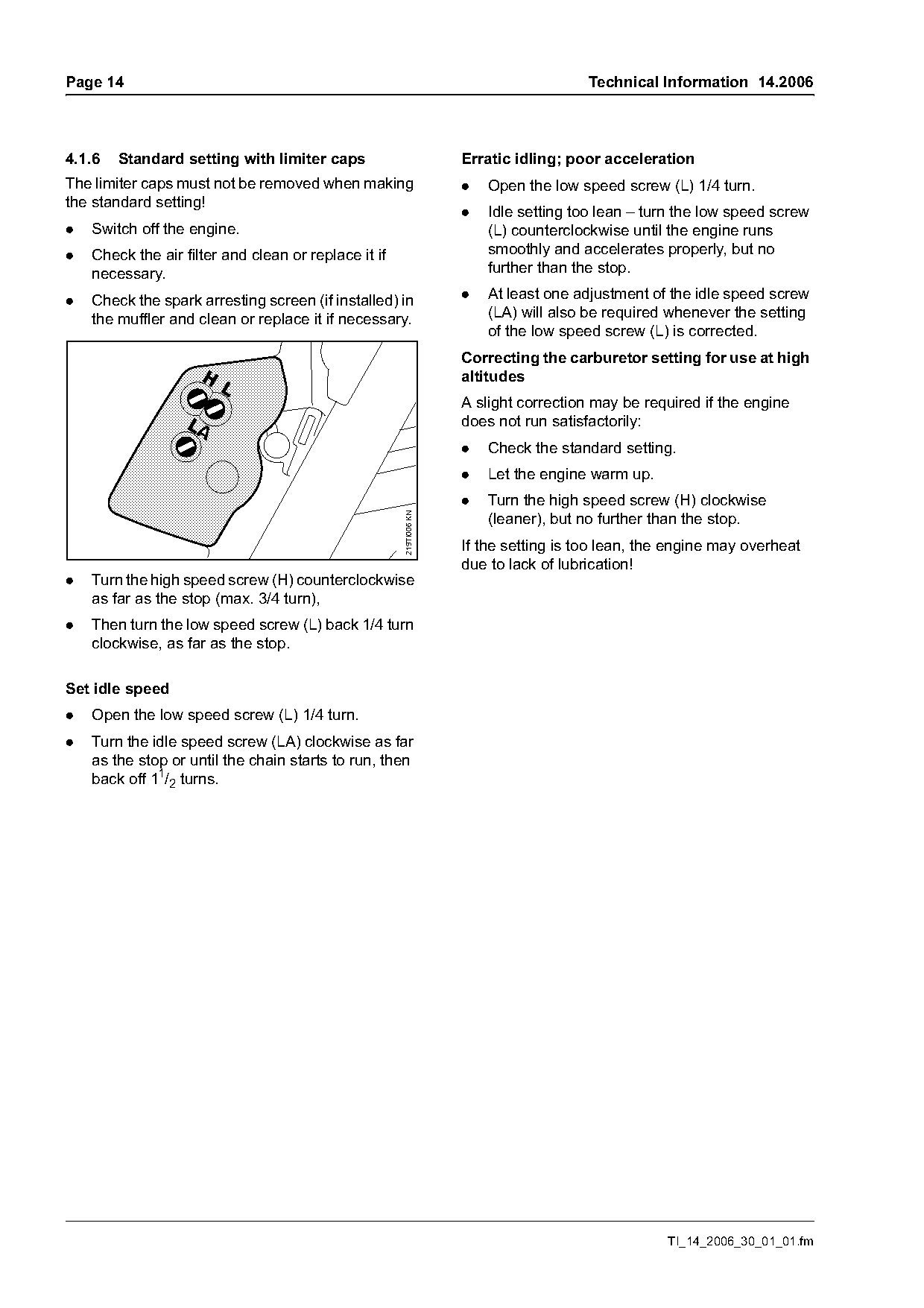
4.1.6   Standard setting with limiter caps                          Erratic idling; poor acceleration
The limiter caps must not be removed when making                    .   Open the low speed screw (L) 1/4 turn.
the standard setting!
                                                                    .   Idle setting too lean – turn the low speed screw
.   Switch off the engine.                                              (L) counterclockwise until the engine runs
.   Check the air filter and clean or replace it if                     smoothly and accelerates properly, but no
    necessary.                                                          further than the stop.

.   Check the spark arresting screen (if installed) in              .   At least one adjustment of the idle speed screw
    the muffler and clean or replace it if necessary.                   (LA) will also be required whenever the setting
                                                                        of the low speed screw (L) is corrected.
                                                                    Correcting the carburetor setting for use at high
                                                                    altitudes
                                                                    A slight correction may be required if the engine
                                                                    does not run satisfactorily:
                                                                    .   Check the standard setting.
                                                                    .   Let the engine warm up.
                                                                    .   Turn the high speed screw (H) clockwise
                                                      219TI006 KN

                                                                        (leaner), but no further than the stop.
                                                                    If the setting is too lean, the engine may overheat
                                                                    due to lack of lubrication!
.   Turn the high speed screw (H) counterclockwise
    as far as the stop (max. 3/4 turn),
.   Then turn the low speed screw (L) back 1/4 turn
    clockwise, as far as the stop.

Set idle speed
.   Open the low speed screw (L) 1/4 turn.
.   Turn the idle speed screw (LA) clockwise as far
    as the stop or until the chain starts to run, then
    back off 11/2 turns.

                                                                                                   TI_14_2006_30_01_01.fm
Page 15 of 16
Text of page 15 — search, copy, screen readers
Technical Information 14.2006                                                                                       Page 15

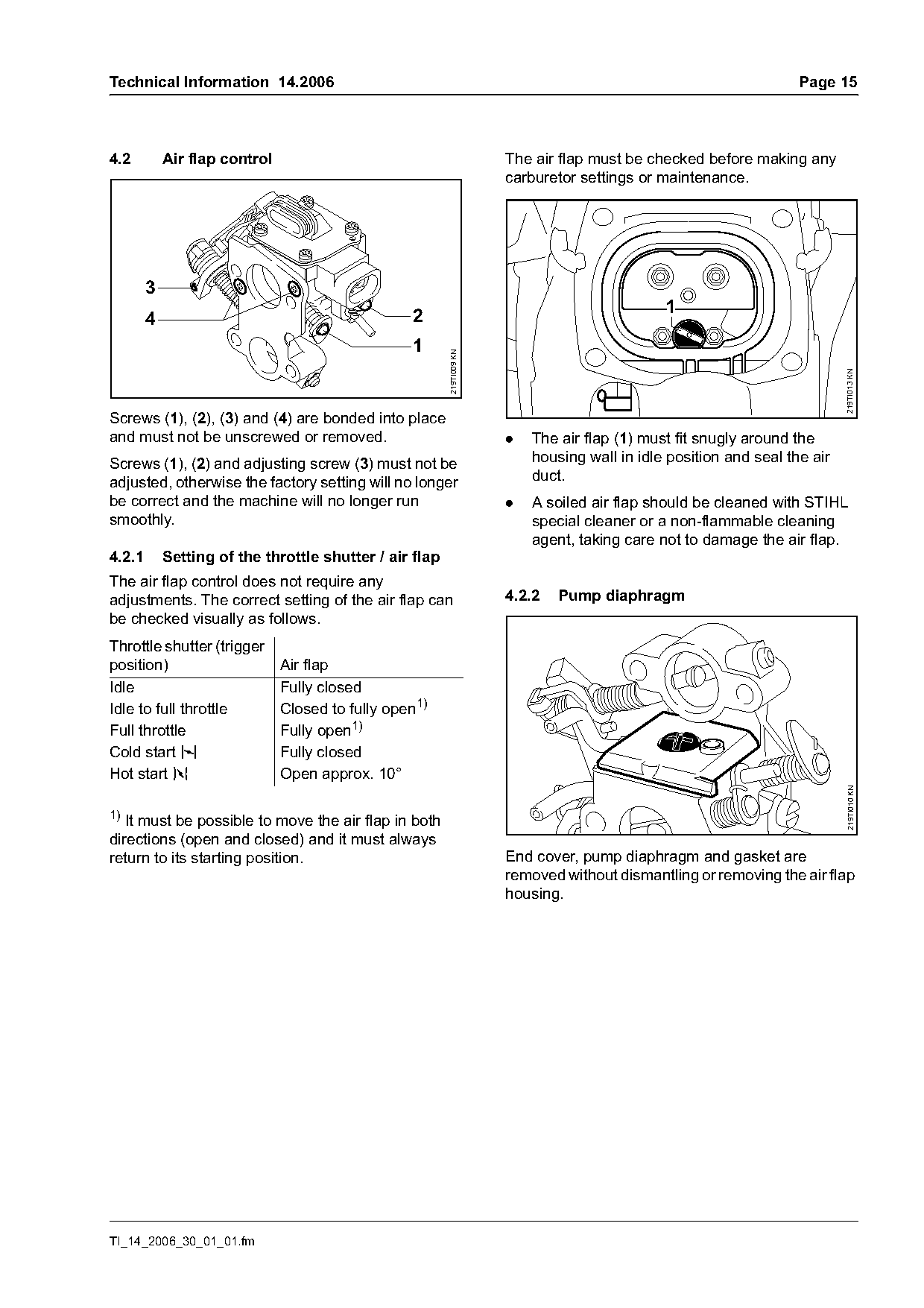
4.2         Air flap control                                           The air flap must be checked before making any
                                                                       carburetor settings or maintenance.

        3
                                                                                               1
        4                                         2
                                                  1

                                                         219TI009 KN

                                                                                                                            219TI013 KN
Screws (1), (2), (3) and (4) are bonded into place
and must not be unscrewed or removed.                                  .   The air flap (1) must fit snugly around the
Screws (1), (2) and adjusting screw (3) must not be                        housing wall in idle position and seal the air
adjusted, otherwise the factory setting will no longer                     duct.
be correct and the machine will no longer run                          .   A soiled air flap should be cleaned with STIHL
smoothly.                                                                  special cleaner or a non-flammable cleaning
                                                                           agent, taking care not to damage the air flap.
4.2.1       Setting of the throttle shutter / air flap
The air flap control does not require any
adjustments. The correct setting of the air flap can                   4.2.2   Pump diaphragm
be checked visually as follows.
Throttle shutter (trigger
position)                      Air flap
Idle                           Fully closed
Idle to full throttle          Closed to fully open1)
Full throttle                  Fully open1)
Cold start l                   Fully closed
Hot start n                    Open approx. 10°

                                                                                                                             219TI010 KN
1)
   It must be possible to move the air flap in both
directions (open and closed) and it must always
return to its starting position.                                       End cover, pump diaphragm and gasket are
                                                                       removed without dismantling or removing the air flap
                                                                       housing.

TI_14_2006_30_01_01.fm
Page 16 of 16
Text of page 16 — search, copy, screen readers
Page 16                                                                             Technical Information 14.2006

4.3     Dual chain brake system                                   The repair times are specified in minutes.
Chain saws with a dual chain brake system must be                    Repair Description                      MS 441
operated with high-quality chain lubricant in order to
                                                                  1  Replace crankcase, crankcase             140
ensure reliable operation. If organic biogradeable
                                                                     gasket or re-seal crankcase.
chain lubricant is to be used, only STIHL BioPlus
                                                                     Includes air leak test.
may be used!
Unsuitable oils will lead to premature failure of the             2 Replace cylinder shroud.                   15
chain brake due to resin build-up.                                3 Replace crankshaft main bearing(s).       130
                                                                     Includes air leak test.
4.4     Tightening torques                                        4 Replace crankshaft seal(s). Includes       60
                                                                     air leak test.
The tightening torques for the MS 441 are specified
in the service manual STIHL MS 441.                               5 Perform engine air leak test.              30
                                                                  6 Replace cylinder and/or piston.            60
4.5     Service note                                                 Includes air leak test and repair of
                                                                     components causing failure.
The service manual STIHL MS 441 is available for
servicing and repair of the STIHL MS 441.                         7 Replace ignition module or flywheel.       25
                                                                     Includes stop circuit test.
4.6     Serial No.                                                8 Replace fuel tank line, tank vent, or      25
                                                                     fuel pick-up body.
                                                                  9 Replace intake manifold or intake          25
                                                                     flange, including leak test.
                                                                  10 Repair or replace carburetor.             30
                                                                     Includes fuel system testing.
                                                                  11 Replace fuel tank housing.                35
                                                                  12 Replace oil pick-up/delivery line.        20
                                                                     Includes oil output test.
                                                                  13 Replace oil pump and/or pump drive        20
                                                                     gear. Includes oil output test.
                                                    219TI007 KN

                                                                  14 Replace rear handle frame or              30
                                                                     handle housing.
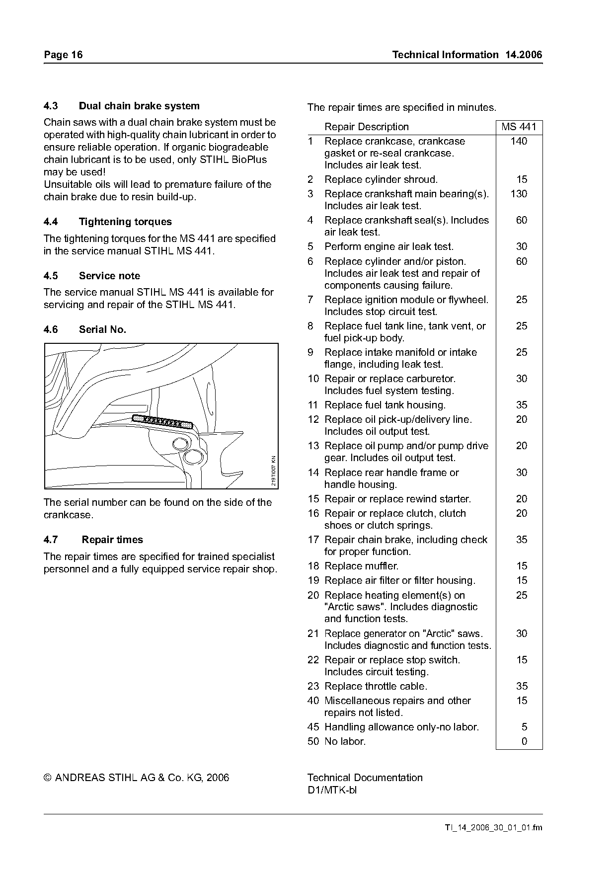
The serial number can be found on the side of the                 15 Repair or replace rewind starter.         20
crankcase.                                                        16 Repair or replace clutch, clutch          20
                                                                     shoes or clutch springs.
4.7     Repair times                                              17 Repair chain brake, including check       35
The repair times are specified for trained specialist                for proper function.
personnel and a fully equipped service repair shop.               18 Replace muffler.                          15
                                                                  19 Replace air filter or filter housing.     15
                                                                  20 Replace heating element(s) on             25
                                                                     "Arctic saws". Includes diagnostic
                                                                     and function tests.
                                                                  21 Replace generator on "Arctic" saws.       30
                                                                     Includes diagnostic and function tests.
                                                                  22 Repair or replace stop switch.            15
                                                                     Includes circuit testing.
                                                                  23 Replace throttle cable.                   35
                                                                  40 Miscellaneous repairs and other           15
                                                                     repairs not listed.
                                                                  45 Handling allowance only-no labor.          5
                                                                  50 No labor.                                  0

© ANDREAS STIHL AG & Co. KG, 2006                                 Technical Documentation
                                                                  D1/MTK-bl

                                                                                                TI_14_2006_30_01_01.fm
Most of these PDFs embed fonts with a shifted character map, so the text above was recovered rather than copied — read it as a faithful but imperfect transcription, and treat the page image above each block as the authority where the two disagree — the figures exist only there, because they are vector drawings that text extraction cannot keep.