Technical Information · issue 49 of 2006
Intelligent Engine Management; Diagnosis; Servicing; Summary; Special tool
IssueTI 49/2006
Engine family 1133
Full text
Page 1 of 17
Text of page 1 — search, copy, screen readers
STIH)

Technical Information                                 49.2006

  Chain saw STIHL MS 280 – Series 1133

  Contents
  1.   Intelligent Engine Management
  2.   Diagnosis
  3.   Servicing
  4.   Summary
  5.   Special tool

  1.      Intelligent Engine Management
  Chain saws MS 280 and MS 280 C will be equipped
  with Intelligent Engine Management in the future.

  TI_49_2006_30_01_01.fm                               englisch / English USA
Page 2 of 17
Text of page 2 — search, copy, screen readers
Page 2                                                                      Technical Information 49.2006

On these chain saws the full load mix and maximum         1.1.2   Ignition module
engine speed will be electronically controlled.           The ignition module has an integral microprocessor
Intelligent Engine Management is designed to              to monitor the engine speed and regulate the
provide optimum engine power, very good                   solenoid valve.
acceleration, a constant maximum speed and                Spare parts/Service note
automatic adaptation to conditions (e.g. at high
altitudes), without manual adjustments.                   The new ignition module can be identified by the
                                                          impressed designation. See 3.1.1. Ignition
Machines with Intelligent Engine Management are           module/flywheel combination.
identifiable by the carburetor box cover. These
machines do not have the high speed screw H or,
consequently, the hole in the carburetor box cover to
allow adjustment.

1.1      Components

1.1.1    Carburetor/solenoid valve

The high speed screw H is replaced by the solenoid
valve (1). The fuel delivery is controlled by the
electronically switched solenoid valve.
The solenoid valve operates digitally. It opens and
closes 30 times per second. The “opening” and
“closing” times are variable, i.e. the fuel flow can be
controlled by the valve.
Idle mixture adjustments can be made by means of
the low speed screw L as previously.
The carburetor does not have a compensator.
The compensator function, that is, keeping the mix
proportions constant irrespective of how dirty the air
filter is, is performed by the regulating system in the
ignition module and solenoid valve.

                                                                                       TI_49_2006_30_01_01.fm
Page 3 of 17
Text of page 3 — search, copy, screen readers
Technical Information 49.2006                                                                            Page 3

1.1.3   Flywheel                                           1.1.5   Filter base
                                                           Intelligent Engine Management provides constant
                                                           mixing, irrespective of how dirty the air filter is.
                                                           The compensator connections are therefore not
                                                           provided on the filter base or on the carburetor.
                                                           Supply of spare parts
                                                           The previous filter base will continue to be available
                                                           for machines without Intelligent Engine
                                                           Management.

                                                           1.1.6   Carburetor box cover
A second pair of poles on the flywheel provides the        The carburetor box cover no longer has the hole for
necessary power supply for the microprocessor and          adjustment of the high speed screw H. With
the solenoid valve.                                        Intelligent Engine Management the high speed
                                                           screw is replaced by the solenoid valve.
Supply of spare parts
                                                           Supply of spare parts
The previous flywheel will continue to be available
for machines without Intelligent Engine                    The previous carburetor box cover will continue to
Management.                                                be available for machines without Intelligent Engine
                                                           Management.

1.1.4   Wiring harness

The connection between the ignition module and
the solenoid valve is made by means of two wires
switched in parallel to the ground wire or short circuit
wire.
Spare parts/Service note
The previous wiring harness, without a terminal for
the solenoid valve, will continue to be available for
machines without Intelligent Engine Management.

TI_49_2006_30_01_01.fm
Page 4 of 17
Text of page 4 — search, copy, screen readers
Page 4                                                                        Technical Information 49.2006

    1.2     Function                                            The next regulating cycle will start again with the
    The microprocessor in the ignition module monitors          solenoid valve closing briefly. A regulating cycle only
    the engine speed and regulates the solenoid valve.          starts if the engine is operated for approximately
                                                                5 seconds under constant conditions.
                                                                The speed change due to the brief leaning of the mix
                                                                is so slight as to be imperceptible to the user.

                                                                1.3      Advantages
                                                                .     Optimum engine performance at all times
                                                                .     Very good acceleration
                                                                .     Constant maximum speed
                                                                .     Automatic adaptation to altered conditions of
                                                                      use e.g. when working at a high altitude

    If the solenoid valve (1) is open for a large part of the
    time within the 30 millisecond switching cycle, the         2.       Diagnosis
    fuel flow is increased.
                                                                The flow charts that follow deal with specific parts
    If, on the other hand, the solenoid valve is open for       diagnosis and trouble-shooting for Intelligent Engine
    a smaller part of the time, the fuel flow is reduced.       Management.
                                                                The flow charts help you to take the correct step at
                                                                the correct time. All other diagnosis and repair
    If the engine is in use under constant conditions for
                                                                operations remain unchanged.
    approximately 5 seconds the solenoid valve closes
    briefly (approx. 1/10 second) and the fuel flow is
    reduced. The current fuel/air mix becomes leaner.
    The resulting engine speed pattern is analysed by
    the microprocessor.
    The following results are possible:
    Engine speed increases
    The mix was too rich before the solenoid valve
    closed – the fuel flow is reduced for next phase of
    operation.
    Engine speed decreases
    The mix was too lean before the solenoid valve
    closed – the fuel flow is increased for the next phase
    of operation.
    Engine speed does not change
    The current carburetor setting is optimal – the
    current setting will be maintained.

                                                                                          TI_49_2006_30_01_01.fm
Page 5 of 17
Text of page 5 — search, copy, screen readers
      Technical Information 49.2006                                                                             Page 5

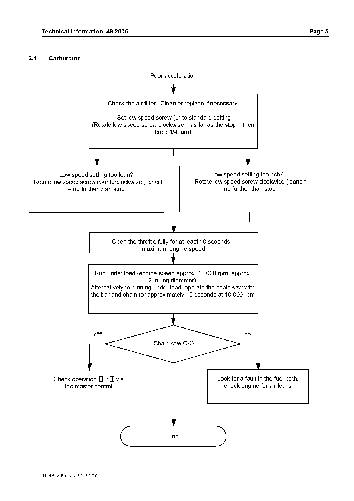
2.1     Carburetor

                                                Poor acceleration

                                Check the air filter. Clean or replace if necessary.

                                   Set low speed screw (L) to standard setting
                         (Rotate low speed screw clockwise – as far as the stop – then
                                                back 1/4 turn)

            Low speed setting too lean?                                 Low speed setting too rich?
– Rotate low speed screw counterclockwise (richer)              – Rotate low speed screw clockwise (leaner)
               – no further than stop                                      – no further than stop

                                 Open the throttle fully for at least 10 seconds –
                                            maximum engine speed

                           Run under load (engine speed approx. 10,000 rpm, approx.
                                               12 in. log diameter) –
                         Alternatively to running under load, operate the chain saw with
                         the bar and chain for approximately 10 seconds at 10,000 rpm

                          yes                                                          no
                                                  Chain saw OK?

          Check operation $ / # via                                        Look for a fault in the fuel path,
             the master control                                              check engine for air leaks

                                                        End

      TI_49_2006_30_01_01.fm
Page 6 of 17
Text of page 6 — search, copy, screen readers
Page 6                                                                       Technical Information 49.2006

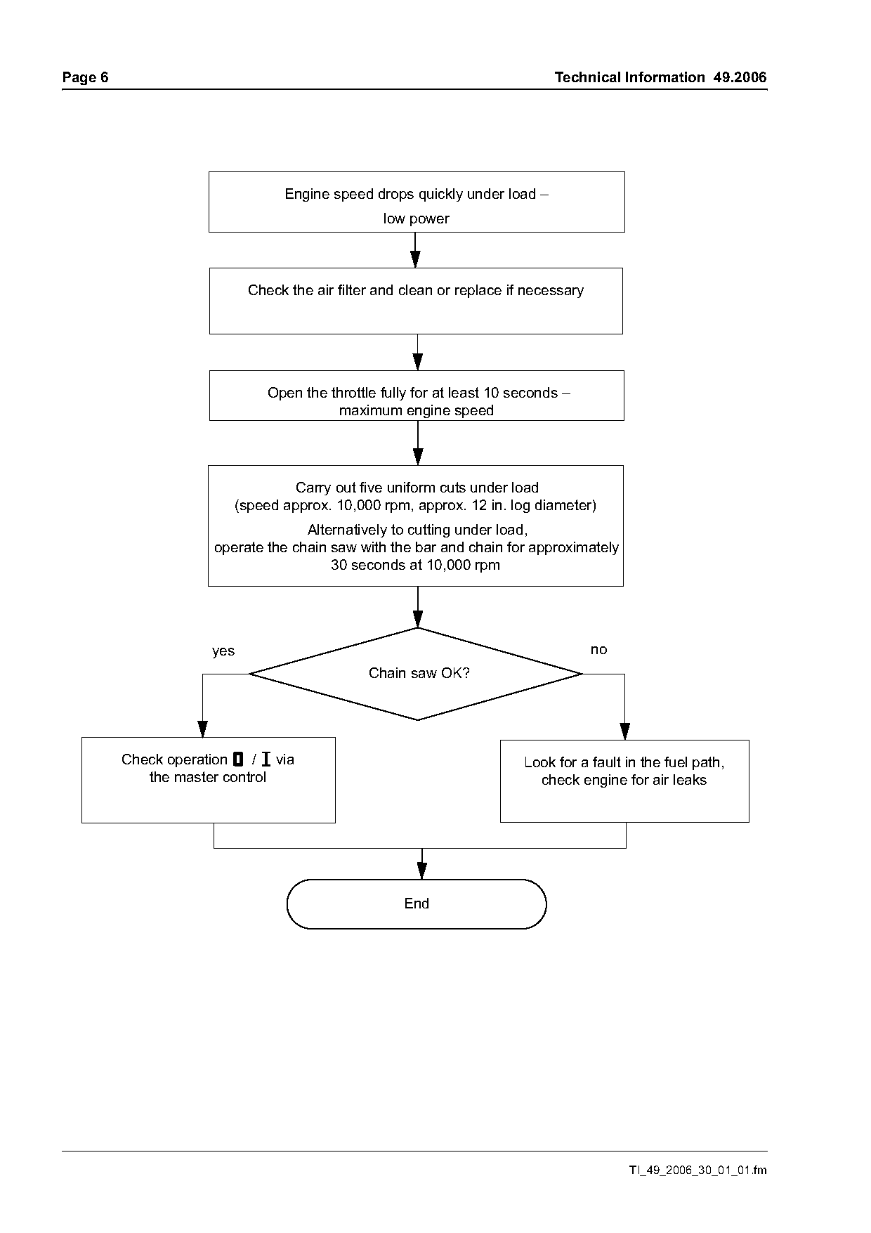
                                 Engine speed drops quickly under load –
                                                 low power

                            Check the air filter and clean or replace if necessary

                               Open the throttle fully for at least 10 seconds –
                                         maximum engine speed

                                  Carry out five uniform cuts under load
                         (speed approx. 10,000 rpm, approx. 12 in. log diameter)
                                    Alternatively to cutting under load,
                      operate the chain saw with the bar and chain for approximately
                                        30 seconds at 10,000 rpm

                      yes                                                            no
                                               Chain saw OK?

         Check operation $ / # via                                      Look for a fault in the fuel path,
            the master control                                            check engine for air leaks

                                                     End

                                                                                          TI_49_2006_30_01_01.fm
Page 7 of 17
Text of page 7 — search, copy, screen readers
Technical Information 49.2006                                                                  Page 7

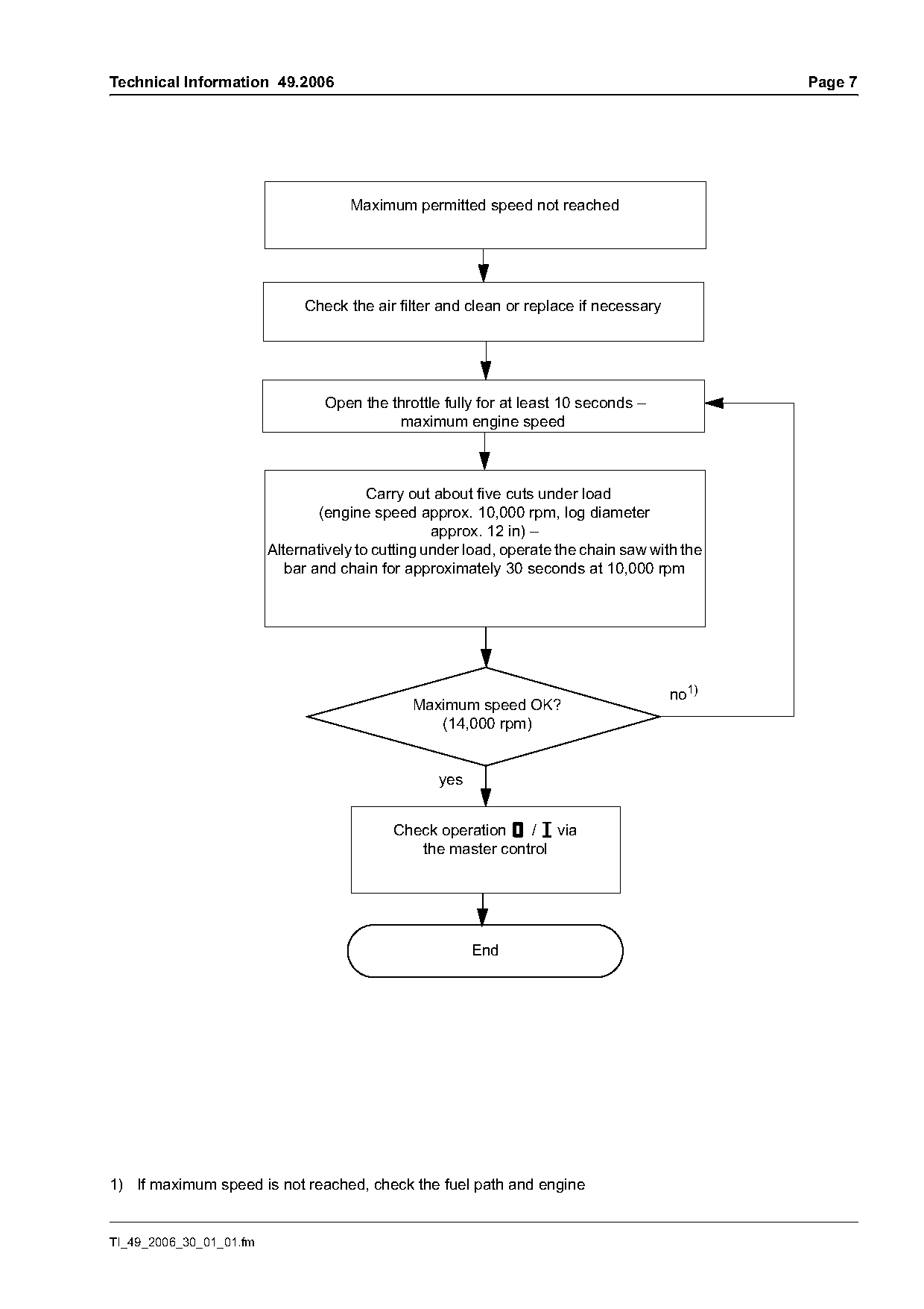
                                     Maximum permitted speed not reached

                              Check the air filter and clean or replace if necessary

                                 Open the throttle fully for at least 10 seconds –
                                           maximum engine speed

                                         Carry out about five cuts under load
                                 (engine speed approx. 10,000 rpm, log diameter
                                                   approx. 12 in) –
                         Alternatively to cutting under load, operate the chain saw with the
                            bar and chain for approximately 30 seconds at 10,000 rpm

                                                                                       no1)
                                               Maximum speed OK?
                                                  (14,000 rpm)

                                                   yes

                                            Check operation $ / # via
                                               the master control

                                                         End

1) If maximum speed is not reached, check the fuel path and engine

TI_49_2006_30_01_01.fm
Page 8 of 17
Text of page 8 — search, copy, screen readers
Page 8                                                                     Technical Information 49.2006

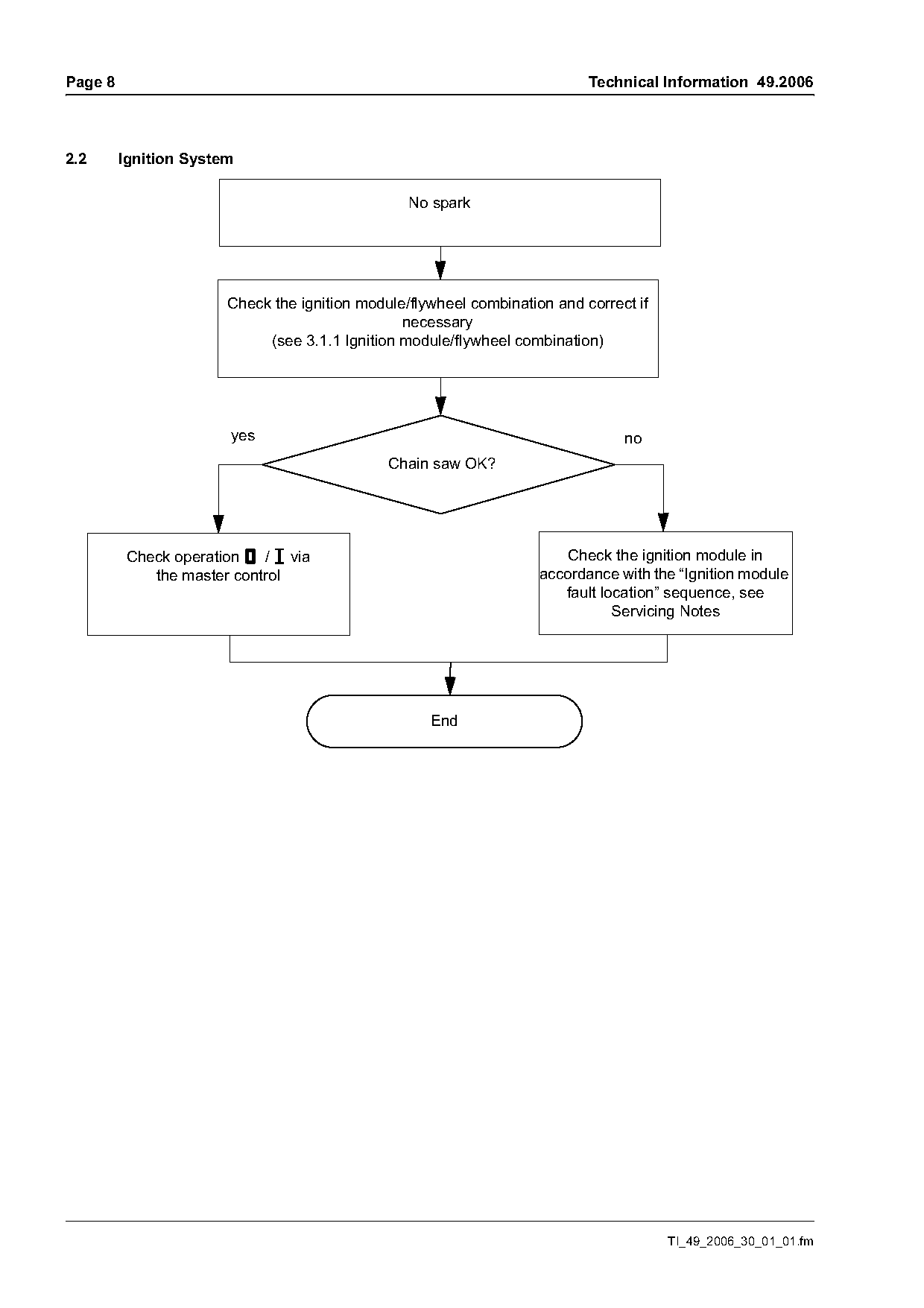
2.2      Ignition System

                                                 No spark

                       Check the ignition module/flywheel combination and correct if
                                                necessary
                            (see 3.1.1 Ignition module/flywheel combination)

                        yes                                                     no
                                              Chain saw OK?

          Check operation $ / # via                                     Check the ignition module in
             the master control                                     accordance with the “Ignition module
                                                                       fault location” sequence, see
                                                                               Servicing Notes

                                                    End

                                                                                       TI_49_2006_30_01_01.fm
Page 9 of 17
Text of page 9 — search, copy, screen readers
Technical Information 49.2006                                                                            Page 9

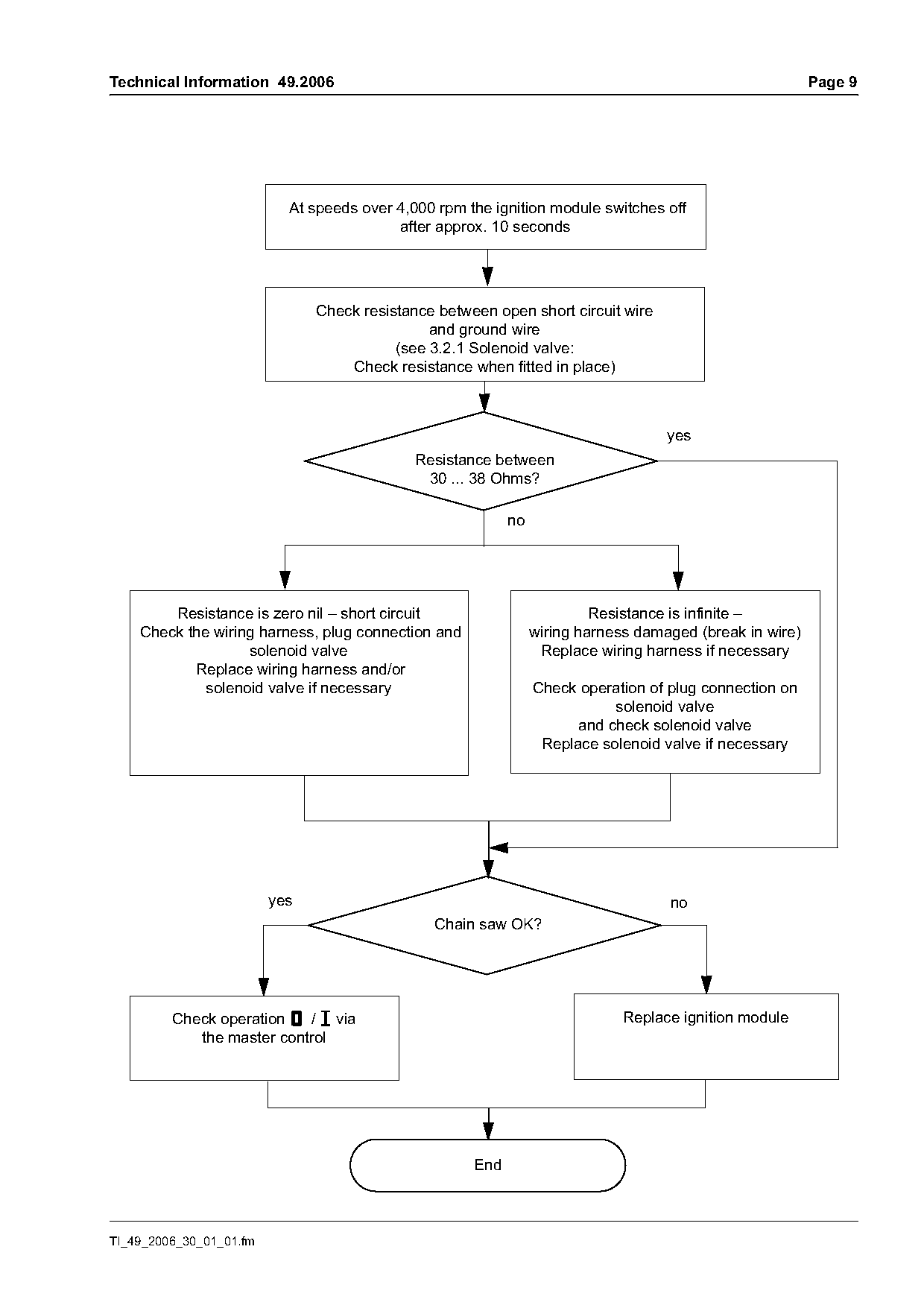
                           At speeds over 4,000 rpm the ignition module switches off
                                          after approx. 10 seconds

                               Check resistance between open short circuit wire
                                               and ground wire
                                          (see 3.2.1 Solenoid valve:
                                   Check resistance when fitted in place)

                                                                                   yes
                                             Resistance between
                                              30 ... 38 Ohms?

        Resistance is zero nil – short circuit                           Resistance is infinite –
    Check the wiring harness, plug connection and               wiring harness damaged (break in wire)
                   solenoid valve                                Replace wiring harness if necessary
           Replace wiring harness and/or
             solenoid valve if necessary                        Check operation of plug connection on
                                                                           solenoid valve
                                                                      and check solenoid valve
                                                                 Replace solenoid valve if necessary

                         yes                                                       no
                                               Chain saw OK?

         Check operation $ / # via                                           Replace ignition module
            the master control

                                                     End

TI_49_2006_30_01_01.fm
Page 10 of 17
Text of page 10 — search, copy, screen readers
Page 10                                                                            Technical Information 49.2006

3.      Servicing                                              3.1.2   Calibrating the ignition module
                                                               A new ignition module can be calibrated after fitting
3.1     Ignition system                                        to ensure an optimum setting
                                                               .   Start the chain saw – the chain and guide bar
3.1.1   Ignition module/flywheel combination
                                                                   must be mounted
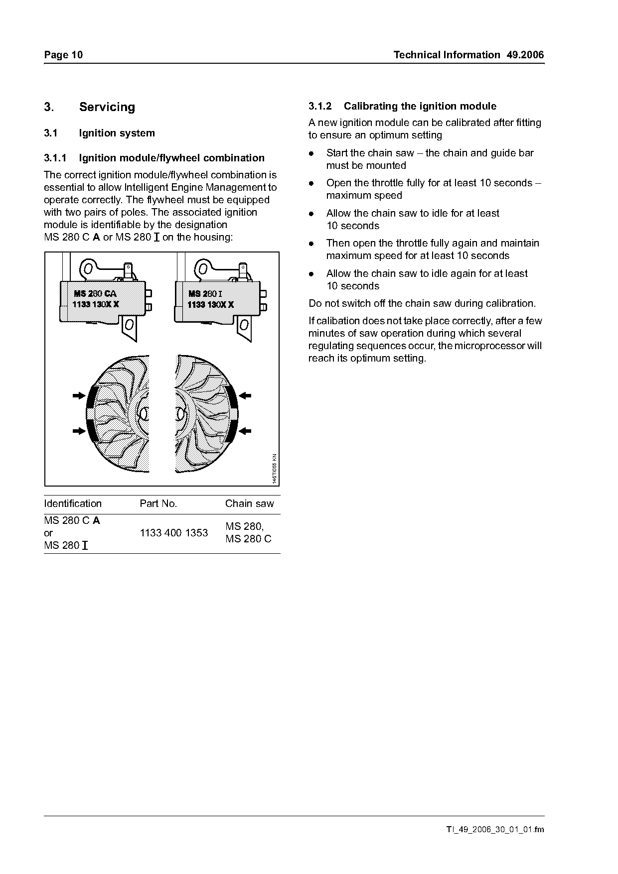
The correct ignition module/flywheel combination is
essential to allow Intelligent Engine Management to            .   Open the throttle fully for at least 10 seconds –
operate correctly. The flywheel must be equipped                   maximum speed
with two pairs of poles. The associated ignition               .   Allow the chain saw to idle for at least
module is identifiable by the designation                          10 seconds
MS 280 C A or MS 280 # on the housing:
                                                               .   Then open the throttle fully again and maintain
                                                                   maximum speed for at least 10 seconds
                                                               .   Allow the chain saw to idle again for at least
                                                                   10 seconds
                                                               Do not switch off the chain saw during calibration.
                                                               If calibation does not take place correctly, after a few
                                                               minutes of saw operation during which several
                                                               regulating sequences occur, the microprocessor will
                                                               reach its optimum setting.
                                                 146TI055 KN

Identification      Part No.           Chain saw
MS 280 C A
                                       MS 280,
or                  1133 400 1353
                                       MS 280 C
MS 280 #

                                                                                                TI_49_2006_30_01_01.fm
Page 11 of 17
Text of page 11 — search, copy, screen readers
Technical Information 49.2006                                                                                       Page 11

3.1.3       Engine stops – ignition module switches                 3.2       Carburetor
            off
The microprocessor continually checks the                           3.2.1     Solenoid valve: Checking resistance
connection between the ignition module and the                                when fitted in place
solenoid valve (resistance test). If the test does not
produce a positive result within 10 seconds at a
speed over 4,000 rpm, the microprocessor switches
off the ignition system and the engine stops.
If the connection with the solenoid valve were to be
severed, the solenoid valve would remain open all
the time. Too much fuel would enter the cylinder and
the fuel/air mix would be too rich. To prevent this, the
microprocessor switches off the ignition system.

Checking operation
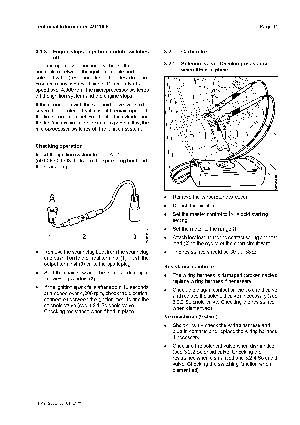
Insert the ignition system tester ZAT 4
(5910 850 4503) between the spark plug boot and
the spark plug.

                                                                    .     Remove the carburetor box cover
                                                                    .     Detach the air filter
                                                                    .     Set the master control to k = cold starting
                                                                          setting
                                                                    .     Set the meter to the range Ω
                                                      000TI036 KN

        1               2                       3                   .     Attach test lead (1) to the contact spring and test
                                                                          lead (2) to the eyelet of the short circuit wire
.   Remove the spark plug boot from the spark plug                  .     The resistance should be 30 …. 38 Ω
    and push it on to the input terminal (1). Push the
    output terminal (3) on to the spark plug.
                                                                    Resistance is infinite
.   Start the chain saw and check the spark jump in
                                                                    .     The wiring harness is damaged (broken cable):
    the viewing window (2).
                                                                          replace wiring harness if necessary
.   If the ignition spark fails after about 10 seconds
                                                                    .     Check the plug-in contact on the solenoid valve
    at a speed over 4,000 rpm, check the electrical
                                                                          and replace the solenoid valve if necessary (see
    connection between the ignition module and the
                                                                          3.2.2 Solenoid valve: Checking the resistance
    solenoid valve (see 3.2.1 Solenoid valve:
                                                                          when dismantled)
    Checking resistance when fitted in place)
                                                                    No resistance (0 Ohm)
                                                                    .     Short circuit – check the wiring harness and
                                                                          plug-in contacts and replace the wiring harness
                                                                          if necessary
                                                                    .     Checking the solenoid valve when dismantled
                                                                          (see 3.2.2 Solenoid valve: Checking the
                                                                          resistance when dismantled and 3.2.4 Solenoid
                                                                          valve: Checking the switching function when
                                                                          dismantled)

TI_49_2006_30_01_01.fm
Page 12 of 17
Text of page 12 — search, copy, screen readers
Page 12                                                                    Technical Information 49.2006

3.2.2   Solenoid valve: Checking the resistance        3.2.3   Solenoid valve: Checking the switching
        when dismantled                                        function when fitted in place
.   Remove the carburetor box cover                    .   Remove the carburetor box cover
.   Detach the air filter                              .   Detach the air filter
.   Unscrew the collar nuts and detach the baffle      .   Set the master control to k = cold starting
    and filter base                                        setting

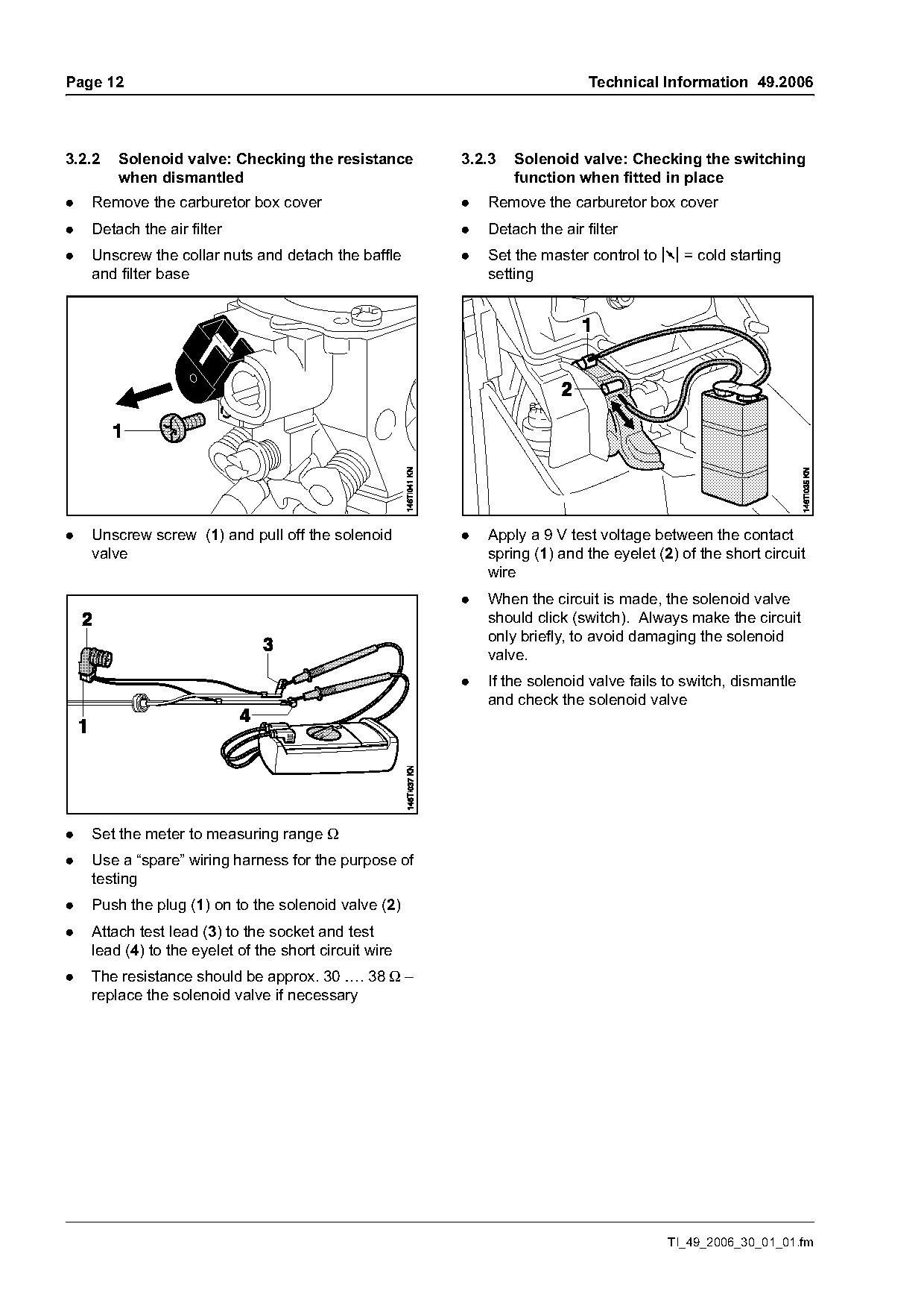
.   Unscrew screw (1) and pull off the solenoid        .   Apply a 9 V test voltage between the contact
    valve                                                  spring (1) and the eyelet (2) of the short circuit
                                                           wire
                                                       .   When the circuit is made, the solenoid valve
                                                           should click (switch). Always make the circuit
                                                           only briefly, to avoid damaging the solenoid
                                                           valve.
                                                       .   If the solenoid valve fails to switch, dismantle
                                                           and check the solenoid valve

.   Set the meter to measuring range Ω
.   Use a “spare” wiring harness for the purpose of
    testing
.   Push the plug (1) on to the solenoid valve (2)
.   Attach test lead (3) to the socket and test
    lead (4) to the eyelet of the short circuit wire
.   The resistance should be approx. 30 …. 38 Ω –
    replace the solenoid valve if necessary

                                                                                       TI_49_2006_30_01_01.fm
Page 13 of 17
Text of page 13 — search, copy, screen readers
Technical Information 49.2006                                                                          Page 13

3.2.4   Solenoid valve: Checking the switching             3.2.7   Limiter cap on the low speed screw (L)
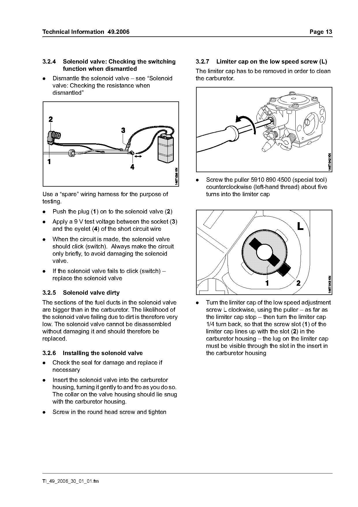
        function when dismantled                           The limiter cap has to be removed in order to clean
.   Dismantle the solenoid valve – see “Solenoid           the carburetor.
    valve: Checking the resistance when
    dismantled”

                                                           .   Screw the puller 5910 890 4500 (special tool)
                                                               counterclockwise (left-hand thread) about five
Use a “spare” wiring harness for the purpose of                turns into the limiter cap
testing.
.   Push the plug (1) on to the solenoid valve (2)
.   Apply a 9 V test voltage between the socket (3)
    and the eyelet (4) of the short circuit wire
.   When the circuit is made, the solenoid valve
    should click (switch). Always make the circuit
    only briefly, to avoid damaging the solenoid
    valve.
.   If the solenoid valve fails to click (switch) –
    replace the solenoid valve

3.2.5   Solenoid valve dirty
The sections of the fuel ducts in the solenoid valve       .   Turn the limiter cap of the low speed adjustment
are bigger than in the carburetor. The likelihood of           screw L clockwise, using the puller – as far as
the solenoid valve failing due to dirt is therefore very       the limiter cap stop – then turn the limiter cap
low. The solenoid valve cannot be disassembled                 1/4 turn back, so that the screw slot (1) of the
without damaging it and should therefore be                    limiter cap lines up with the slot (2) in the
replaced.                                                      carburetor housing – the lug on the limiter cap
                                                               must be visible through the slot in the insert in
3.2.6   Installing the solenoid valve                          the carburetor housing
.   Check the seal for damage and replace if
    necessary
.   Insert the solenoid valve into the carburetor
    housing, turning it gently to and fro as you do so.
    The collar on the valve housing should lie snug
    with the carburetor housing.
.   Screw in the round head screw and tighten

TI_49_2006_30_01_01.fm
Page 14 of 17
Text of page 14 — search, copy, screen readers
Page 14                                                                        Technical Information 49.2006

                                                           Adjust the specified engine speeds within a
                                                           tolerance range of +/- 200 rpm as follows:

                                                           1.     Use the idle speed screw (LA) to set the
                                                                  engine speed to 3,300 rpm

                                                           2.     Rotate the low speed screw (L) clockwise or
                                                                  counterclockwise to obtain maximum engine
                                                                  speed

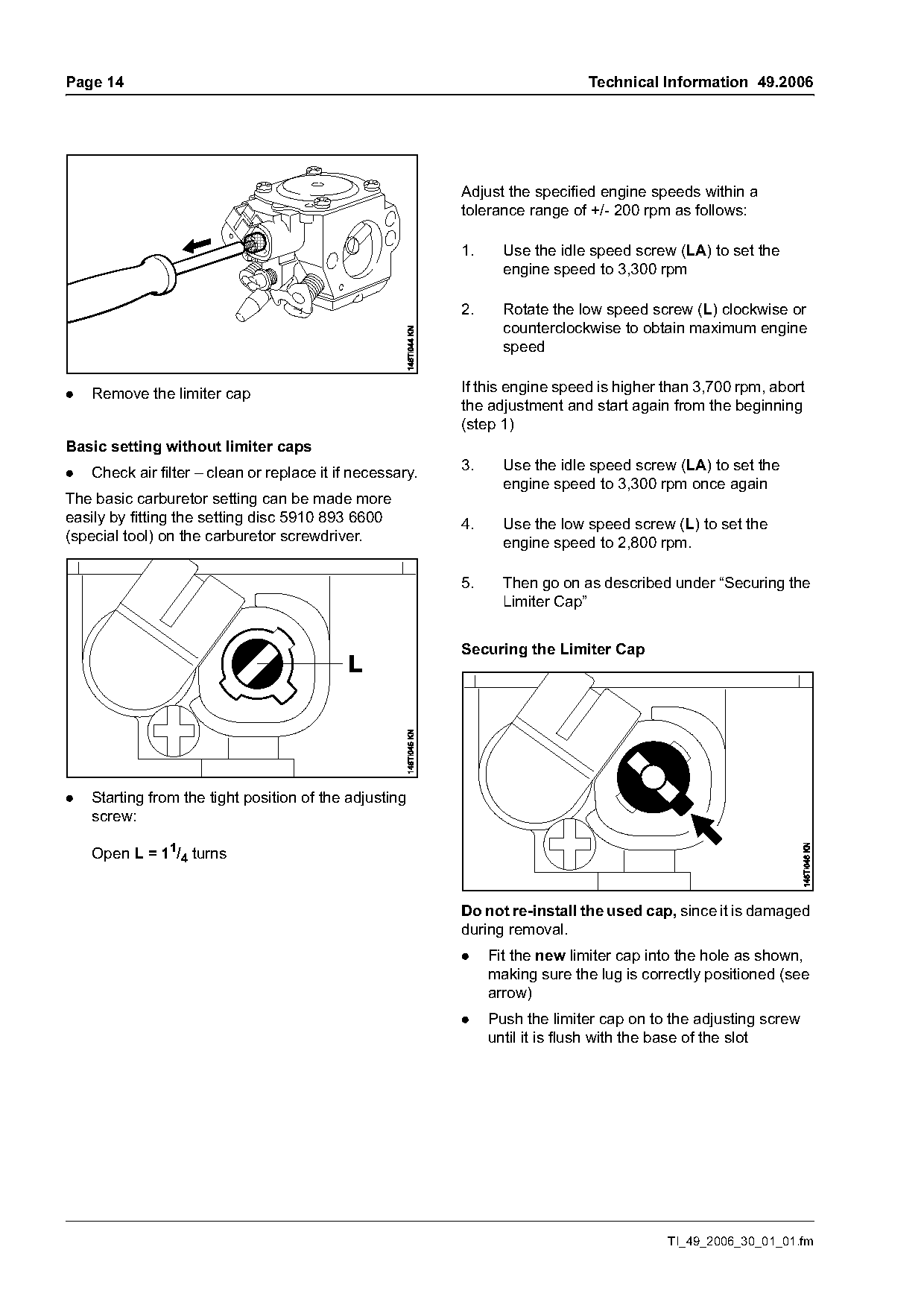
.   Remove the limiter cap                                 If this engine speed is higher than 3,700 rpm, abort
                                                           the adjustment and start again from the beginning
                                                           (step 1)
Basic setting without limiter caps
                                                           3.     Use the idle speed screw (LA) to set the
.   Check air filter – clean or replace it if necessary.
                                                                  engine speed to 3,300 rpm once again
The basic carburetor setting can be made more
easily by fitting the setting disc 5910 893 6600           4.     Use the low speed screw (L) to set the
(special tool) on the carburetor screwdriver.                     engine speed to 2,800 rpm.

                                                           5.     Then go on as described under “Securing the
                                                                  Limiter Cap”

                                                           Securing the Limiter Cap

.   Starting from the tight position of the adjusting
    screw:

    Open L = 11/4 turns

                                                           Do not re-install the used cap, since it is damaged
                                                           during removal.
                                                           .    Fit the new limiter cap into the hole as shown,
                                                                making sure the lug is correctly positioned (see
                                                                arrow)
                                                           .    Push the limiter cap on to the adjusting screw
                                                                until it is flush with the base of the slot

                                                                                          TI_49_2006_30_01_01.fm
Page 15 of 17
Text of page 15 — search, copy, screen readers
Technical Information 49.2006                                                                        Page 15

3.2.8   Carburetor setting instructions for the         Speed erratic when idling; poor acceleration
        user
                                                        .   Adjust the low speed screw (L) to the standard
Standard setting                                            setting
.   Switch off engine                                   .   Turn the low speed screw (L) counterclockwise
.   Check the air filter – clean or replace it if           until the engine runs and accelerates smoothly
    necessary.                                              – but no further than the stop

.   Check the spark arresting screen in the muffler     .   Open the throttle fully for approx. 10 seconds,
    (if fitted) and clean or replace as necessary.          with the chain and guide bar fitted.

.   Check fuel filter and replace if necessary          .   Carry out a cut under full load.

.   Rotate the low speed screw (L) clockwise as far
    as the stop. Then turn back 1/4 turn.               It is usually necessary to change the setting of the
                                                        idle speed screw (LA) after every correction to the
                                                        low speed screw (L).
Setting the idle speed
.   Engine stops when idling                            Operation in different conditions
.   Adjust the low speed screw (L) to the standard      The full load mix and maximum engine speed adjust
    setting.                                            automatically to different conditions (e.g. working at
.   Turn the idle speed screw (LA) clockwise until      high altitude).
    the chain begins to run, then turn the screw back   The automatic adaptation of the optimal engine
    one turn.                                           power can be speeded up as follows:
                                                        .   Open the throttle fully for approx. 10 seconds,
Saw chain rotates at idle speed                             with the chain and guide bar fitted.
.   Adjust the low speed screw (L) to the standard      .   Carry out five uniform cuts under full load.
    setting
.   Turn the idle speed screw (LA)
    counterclockwise until the chain stops running –
    then turn another turn in the same direction.

TI_49_2006_30_01_01.fm
Page 16 of 17
Text of page 16 — search, copy, screen readers
Page 16                                                                   Technical Information 49.2006

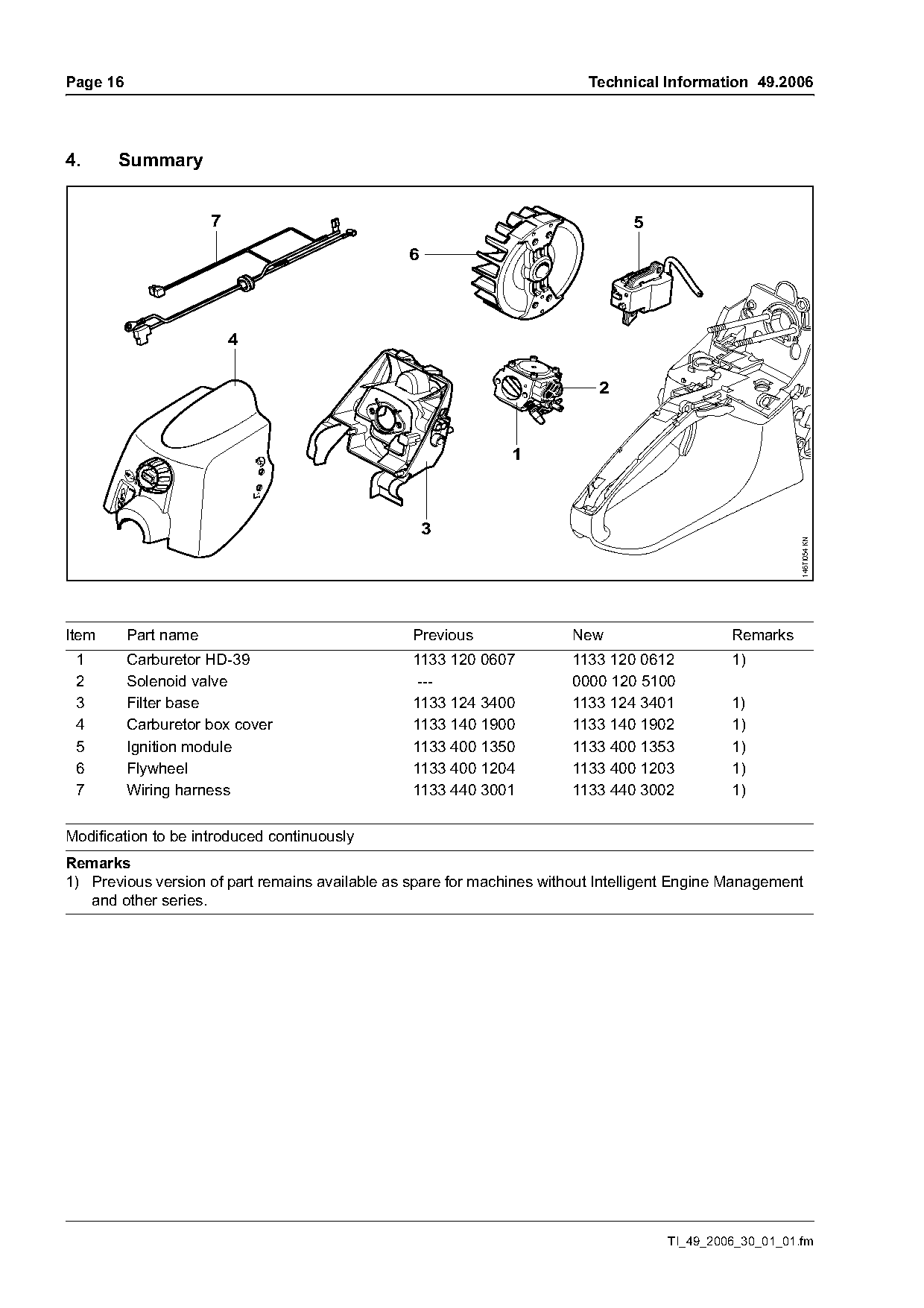
4.     Summary

                      7                                                         5
                                                6


                                                                                                         146TI054 KN
Item      Part name                              Previous               New                   Remarks
 1        Carburetor HD-39                       1133 120 0607          1133 120 0612         1)
 2        Solenoid valve                          ---                   0000 120 5100
 3        Filter base                            1133 124 3400          1133 124 3401         1)
 4        Carburetor box cover                   1133 140 1900          1133 140 1902         1)
 5        Ignition module                        1133 400 1350          1133 400 1353         1)
 6        Flywheel                               1133 400 1204          1133 400 1203         1)
 7        Wiring harness                         1133 440 3001          1133 440 3002         1)

Modification to be introduced continuously
Remarks
1) Previous version of part remains available as spare for machines without Intelligent Engine Management
   and other series.

                                                                                     TI_49_2006_30_01_01.fm
Page 17 of 17
Text of page 17 — search, copy, screen readers
Technical Information 49.2006                                                                      Page 17

5.      Special tool                                    5.2    Wiring harness 1133 440 3002

5.1     Tachometer

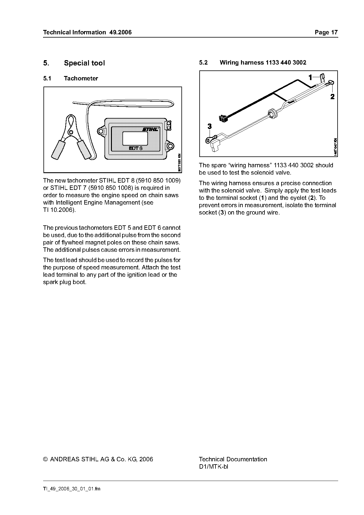
                                                        The spare “wiring harness” 1133 440 3002 should
                                                        be used to test the solenoid valve.
The new tachometer STIHL EDT 8 (5910 850 1009)          The wiring harness ensures a precise connection
or STIHL EDT 7 (5910 850 1008) is required in           with the solenoid valve. Simply apply the test leads
order to measure the engine speed on chain saws         to the terminal socket (1) and the eyelet (2). To
with Intelligent Engine Management (see                 prevent errors in measurement, isolate the terminal
TI 10.2006).                                            socket (3) on the ground wire.

The previous tachometers EDT 5 and EDT 6 cannot
be used, due to the additional pulse from the second
pair of flywheel magnet poles on these chain saws.
The additional pulses cause errors in measurement.
The test lead should be used to record the pulses for
the purpose of speed measurement. Attach the test
lead terminal to any part of the ignition lead or the
spark plug boot.

© ANDREAS STIHL AG & Co. KG, 2006                       Technical Documentation
                                                        D1/MTK-bl

TI_49_2006_30_01_01.fm
Most of these PDFs embed fonts with a shifted character map, so the text above was recovered rather than copied — read it as a faithful but imperfect transcription, and treat the page image above each block as the authority where the two disagree — the figures exist only there, because they are vector drawings that text extraction cannot keep.