Technical Information · issue 27 of 2009
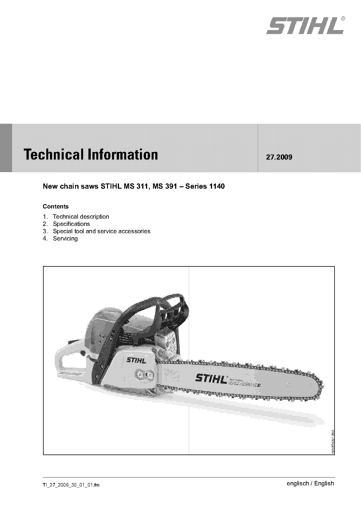
New chain saws STIHL MS 311, MS 391
IssueTI 27/2009
Engine family 1140
Full text
Page 1 of 8
Text of page 1 — search, copy, screen readers
STIH)

Technical Information                                 27.2009

  New chain saws STIHL MS 311, MS 391 – Series 1140

  Contents
  1.   Technical description
  2.   Specifications
  3.   Special tool and service accessories
  4.   Servicing

  TI_27_2009_30_01_01.fm                                   englisch / English
Page 2 of 8
Text of page 2 — search, copy, screen readers
Page 2                                                                             Technical Information 27.2009

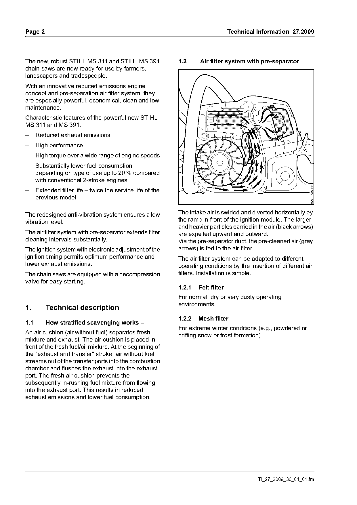
The new, robust STIHL MS 311 and STIHL MS 391                1.2     Air filter system with pre-separator
chain saws are now ready for use by farmers,
landscapers and tradespeople.
With an innovative reduced emissions engine
concept and pre-separation air filter system, they
are especially powerful, economical, clean and low-
maintenance.
Characteristic features of the powerful new STIHL
MS 311 and MS 391:
–     Reduced exhaust emissions
–     High performance
–     High torque over a wide range of engine speeds
–     Substantially lower fuel consumption –
      depending on type of use up to 20 % compared
      with conventional 2-stroke engines

                                                                                                                  0001TI002 KN
–     Extended filter life – twice the service life of the
      previous model

The redesigned anti-vibration system ensures a low           The intake air is swirled and diverted horizontally by
vibration level.                                             the ramp in front of the ignition module. The larger
                                                             and heavier particles carried in the air (black arrows)
The air filter system with pre-separator extends filter      are expelled upward and outward.
cleaning intervals substantially.                            Via the pre-separator duct, the pre-cleaned air (gray
The ignition system with electronic adjustment of the        arrows) is fed to the air filter.
ignition timing permits optimum performance and              The air filter system can be adapted to different
lower exhaust emissions.                                     operating conditions by the insertion of different air
The chain saws are equipped with a decompression             filters. Installation is simple.
valve for easy starting.
                                                             1.2.1   Felt filter
                                                             For normal, dry or very dusty operating
                                                             environments.
1.        Technical description
                                                             1.2.2   Mesh filter
1.1       How stratified scavenging works –
                                                             For extreme winter conditions (e.g., powdered or
An air cushion (air without fuel) separates fresh
                                                             drifting snow or frost formation).
mixture and exhaust. The air cushion is placed in
front of the fresh fuel/oil mixture. At the beginning of
the "exhaust and transfer" stroke, air without fuel
streams out of the transfer ports into the combustion
chamber and flushes the exhaust into the exhaust
port. The fresh air cushion prevents the
subsequently in-rushing fuel mixture from flowing
into the exhaust port. This results in reduced
exhaust emissions and lower fuel consumption.

                                                                                             TI_27_2009_30_01_01.fm
Page 3 of 8
Text of page 3 — search, copy, screen readers
Technical Information 27.2009                                                                                    Page 3

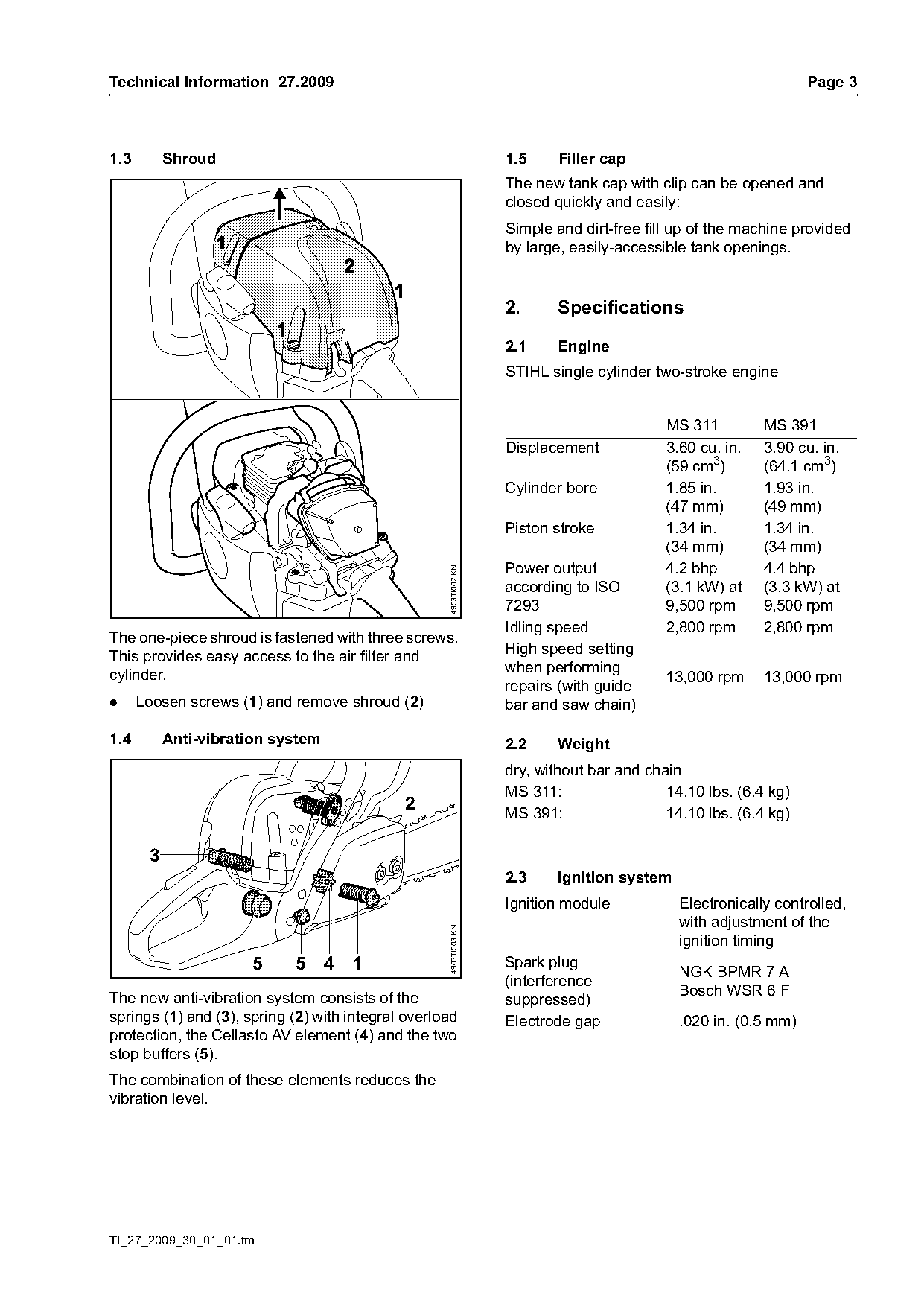
1.3        Shroud                                                  1.5    Filler cap
                                                                   The new tank cap with clip can be opened and
                                                                   closed quickly and easily:
                                                                   Simple and dirt-free fill up of the machine provided
                                                                   by large, easily-accessible tank openings.

                                                                   2.     Specifications

                                                                   2.1    Engine
                                                                   STIHL single cylinder two-stroke engine

                                                                                           MS 311         MS 391
                                                                   Displacement            3.60 cu. in.   3.90 cu. in.
                                                                                           (59 cm3)       (64.1 cm3)
                                                                   Cylinder bore           1.85 in.       1.93 in.
                                                                                           (47 mm)        (49 mm)
                                                                   Piston stroke           1.34 in.       1.34 in.
                                                                                           (34 mm)        (34 mm)
                                                                   Power output            4.2 bhp        4.4 bhp
                                                    4903TI002 KN

                                                                   according to ISO        (3.1 kW) at    (3.3 kW) at
                                                                   7293                    9,500 rpm      9,500 rpm
                                                                   Idling speed            2,800 rpm      2,800 rpm
The one-piece shroud is fastened with three screws.
This provides easy access to the air filter and                    High speed setting
cylinder.                                                          when performing
                                                                                           13,000 rpm     13,000 rpm
                                                                   repairs (with guide
.     Loosen screws (1) and remove shroud (2)                      bar and saw chain)

1.4        Anti-vibration system                                   2.2    Weight
                                                                   dry, without bar and chain
                                                                   MS 311:                 14.10 lbs. (6.4 kg)
                                             2                     MS 391:                 14.10 lbs. (6.4 kg)

       3
                                                                   2.3    Ignition system
                                                                   Ignition module           Electronically controlled,
                                                                                             with adjustment of the
                                                    4903TI003 KN

                                                                                             ignition timing
                      5     5 4      1                             Spark plug
                                                                                             NGK BPMR 7 A
                                                                   (interference
The new anti-vibration system consists of the                                                Bosch WSR 6 F
                                                                   suppressed)
springs (1) and (3), spring (2) with integral overload             Electrode gap             .020 in. (0.5 mm)
protection, the Cellasto AV element (4) and the two
stop buffers (5).
The combination of these elements reduces the
vibration level.

TI_27_2009_30_01_01.fm
Page 4 of 8
Text of page 4 — search, copy, screen readers
Page 4                                                                    Technical Information 27.2009

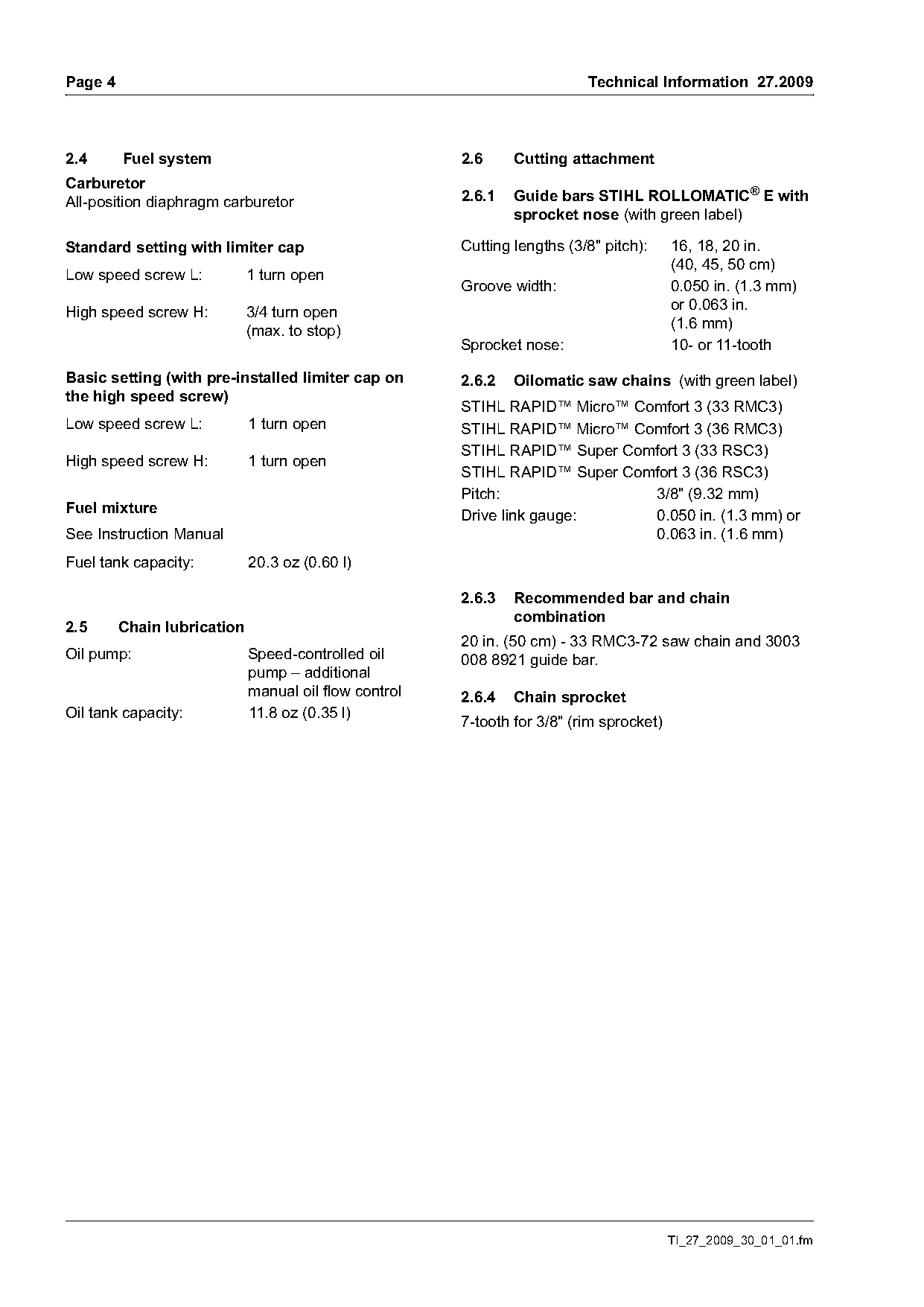
2.4      Fuel system                                   2.6     Cutting attachment
Carburetor
All-position diaphragm carburetor                      2.6.1   Guide bars STIHL ROLLOMATIC® E with
                                                               sprocket nose (with green label)

Standard setting with limiter cap                      Cutting lengths (3/8" pitch):     16, 18, 20 in.
                                                                                         (40, 45, 50 cm)
Low speed screw L:           1 turn open
                                                       Groove width:                     0.050 in. (1.3 mm)
                                                                                         or 0.063 in.
High speed screw H:          3/4 turn open
                                                                                         (1.6 mm)
                             (max. to stop)
                                                       Sprocket nose:                    10- or 11-tooth

Basic setting (with pre-installed limiter cap on       2.6.2   Oilomatic saw chains (with green label)
the high speed screw)
                                                       STIHL RAPID™ Micro™ Comfort 3 (33 RMC3)
Low speed screw L:           1 turn open               STIHL RAPID™ Micro™ Comfort 3 (36 RMC3)
                                                       STIHL RAPID™ Super Comfort 3 (33 RSC3)
High speed screw H:          1 turn open
                                                       STIHL RAPID™ Super Comfort 3 (36 RSC3)
                                                       Pitch:                3/8" (9.32 mm)
Fuel mixture
                                                       Drive link gauge:     0.050 in. (1.3 mm) or
See Instruction Manual                                                       0.063 in. (1.6 mm)
Fuel tank capacity:          20.3 oz (0.60 l)

                                                       2.6.3   Recommended bar and chain
                                                               combination
2.5      Chain lubrication
                                                       20 in. (50 cm) - 33 RMC3-72 saw chain and 3003
Oil pump:                    Speed-controlled oil      008 8921 guide bar.
                             pump – additional
                             manual oil flow control   2.6.4   Chain sprocket
Oil tank capacity:           11.8 oz (0.35 l)
                                                       7-tooth for 3/8" (rim sprocket)

                                                                                         TI_27_2009_30_01_01.fm
Page 5 of 8
Text of page 5 — search, copy, screen readers
Technical Information 27.2009                                                                          Page 5

3.     Special tool and service
       accessories

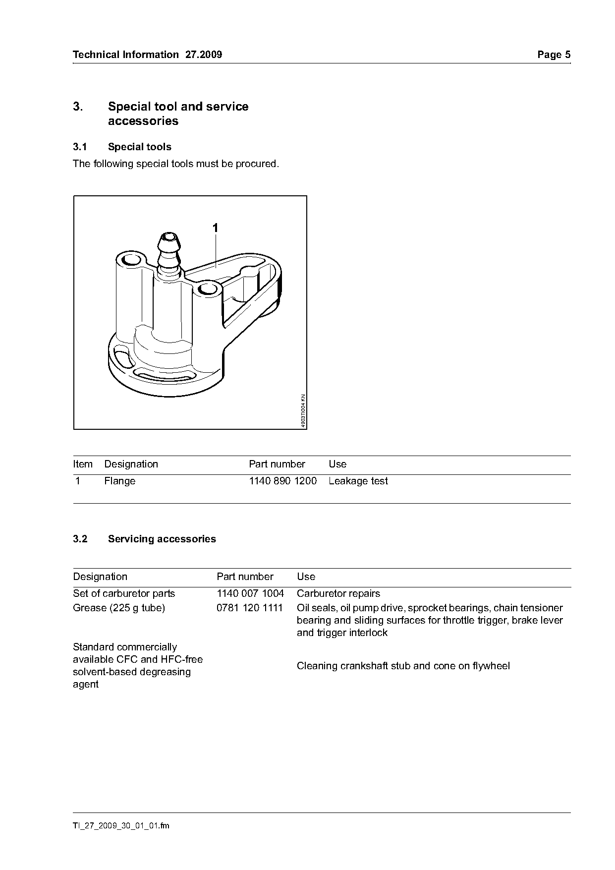
3.1     Special tools
The following special tools must be procured.


                                                4903TI004 KN

Item   Designation                    Part number              Use
1      Flange                         1140 890 1200            Leakage test

3.2     Servicing accessories

Designation                     Part number     Use
Set of carburetor parts        1140 007 1004    Carburetor repairs
Grease (225 g tube)            0781 120 1111    Oil seals, oil pump drive, sprocket bearings, chain tensioner
                                                bearing and sliding surfaces for throttle trigger, brake lever
                                                and trigger interlock
Standard commercially
available CFC and HFC-free
                                                Cleaning crankshaft stub and cone on flywheel
solvent-based degreasing
agent

TI_27_2009_30_01_01.fm
Page 6 of 8
Text of page 6 — search, copy, screen readers
Page 6                                                                         Technical Information 27.2009

3.3      Special accessories for the user

Designation                       Part number       Use
Cover plate kit                   1140 007 1003     Prevents powdered or drifting snow from entering the
                                                    machine under extreme winter conditions (temperatures
                                                    under 14°F (-10 °C), powdered or drifting snow)

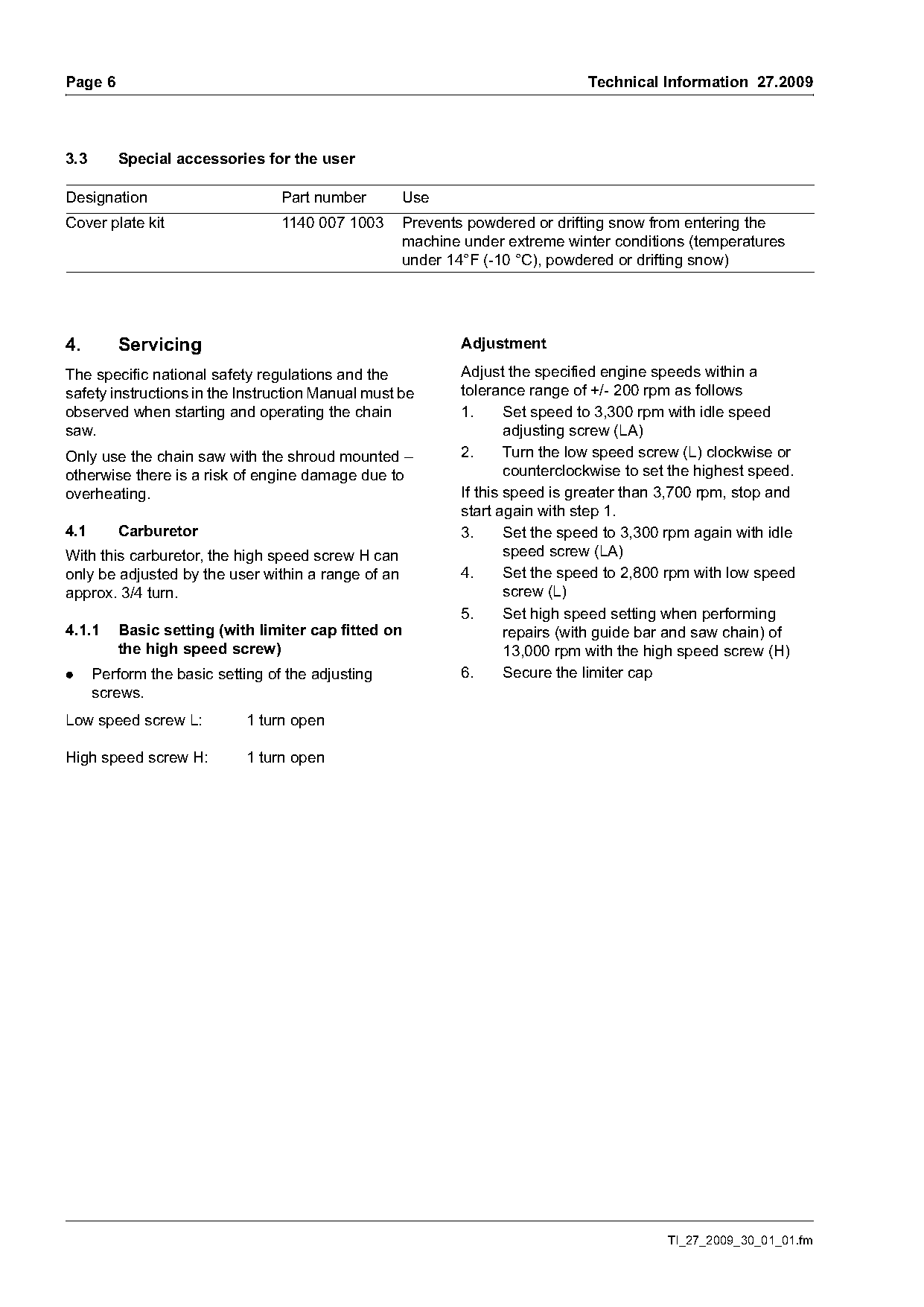
4.       Servicing                                          Adjustment

The specific national safety regulations and the            Adjust the specified engine speeds within a
safety instructions in the Instruction Manual must be       tolerance range of +/- 200 rpm as follows
observed when starting and operating the chain              1.      Set speed to 3,300 rpm with idle speed
saw.                                                                adjusting screw (LA)
Only use the chain saw with the shroud mounted –            2.      Turn the low speed screw (L) clockwise or
otherwise there is a risk of engine damage due to                   counterclockwise to set the highest speed.
overheating.                                                If this speed is greater than 3,700 rpm, stop and
                                                            start again with step 1.
4.1      Carburetor                                         3.      Set the speed to 3,300 rpm again with idle
With this carburetor, the high speed screw H can                    speed screw (LA)
only be adjusted by the user within a range of an           4.      Set the speed to 2,800 rpm with low speed
approx. 3/4 turn.                                                   screw (L)
                                                            5.      Set high speed setting when performing
4.1.1    Basic setting (with limiter cap fitted on                  repairs (with guide bar and saw chain) of
         the high speed screw)                                      13,000 rpm with the high speed screw (H)
.     Perform the basic setting of the adjusting            6.      Secure the limiter cap
      screws.
Low speed screw L:           1 turn open

High speed screw H:          1 turn open

                                                                                          TI_27_2009_30_01_01.fm
Page 7 of 8
Text of page 7 — search, copy, screen readers
Technical Information 27.2009                                                                                      Page 7

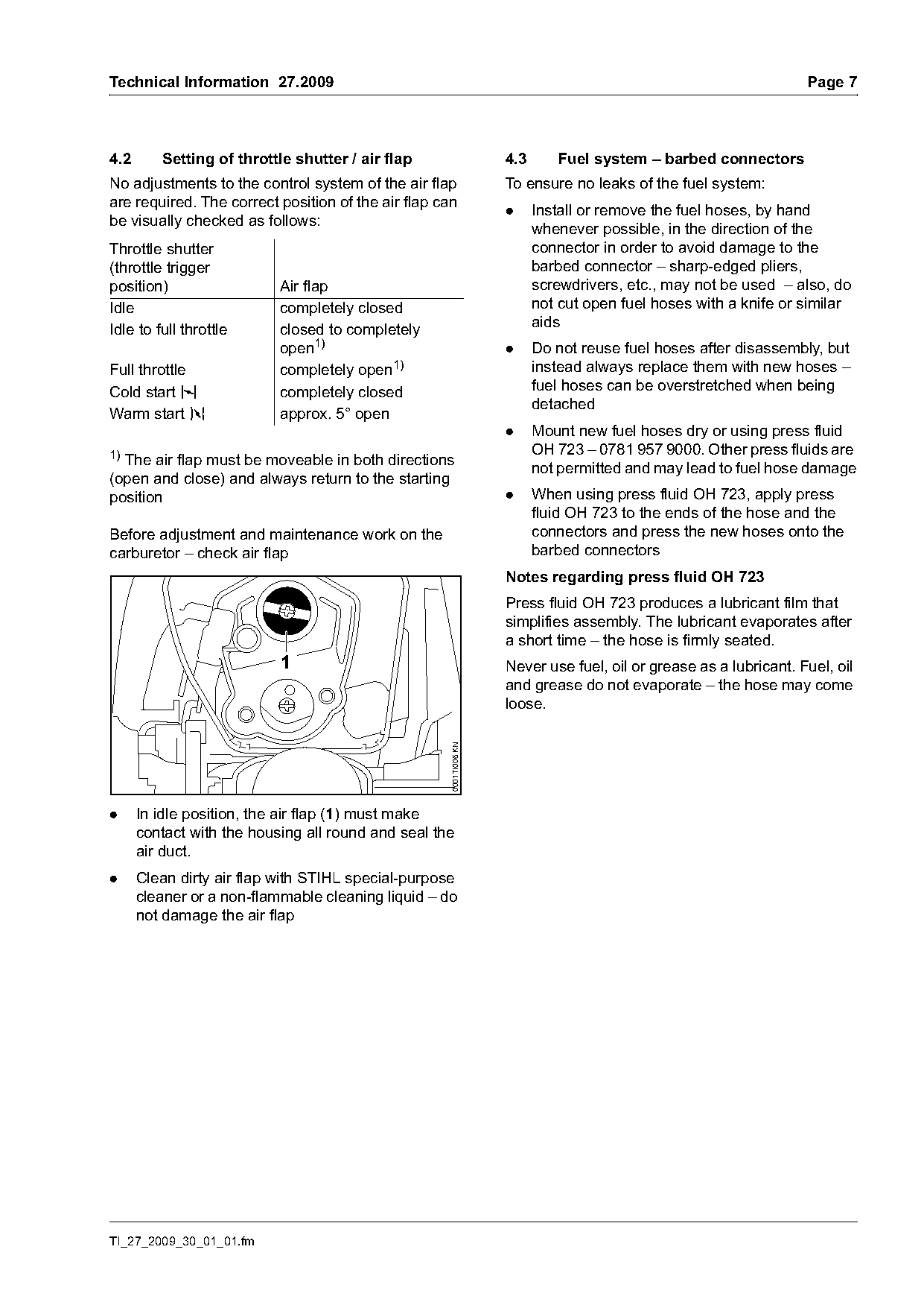
4.2      Setting of throttle shutter / air flap                     4.3      Fuel system – barbed connectors
No adjustments to the control system of the air flap                To ensure no leaks of the fuel system:
are required. The correct position of the air flap can
                                                                    .     Install or remove the fuel hoses, by hand
be visually checked as follows:
                                                                          whenever possible, in the direction of the
Throttle shutter                                                          connector in order to avoid damage to the
(throttle trigger                                                         barbed connector – sharp-edged pliers,
position)                  Air flap                                       screwdrivers, etc., may not be used – also, do
Idle                       completely closed                              not cut open fuel hoses with a knife or similar
                                                                          aids
Idle to full throttle      closed to completely
                           open1)                                   .     Do not reuse fuel hoses after disassembly, but
Full throttle              completely open1)                              instead always replace them with new hoses –
Cold start l               completely closed                              fuel hoses can be overstretched when being
                                                                          detached
Warm start n               approx. 5° open
                                                                    .     Mount new fuel hoses dry or using press fluid
1)                                                                        OH 723 – 0781 957 9000. Other press fluids are
  The air flap must be moveable in both directions                        not permitted and may lead to fuel hose damage
(open and close) and always return to the starting
position                                                            .     When using press fluid OH 723, apply press
                                                                          fluid OH 723 to the ends of the hose and the
Before adjustment and maintenance work on the                             connectors and press the new hoses onto the
carburetor – check air flap                                               barbed connectors
                                                                    Notes regarding press fluid OH 723
                                                                    Press fluid OH 723 produces a lubricant film that
                                                                    simplifies assembly. The lubricant evaporates after
                                                                    a short time – the hose is firmly seated.
                           1                                        Never use fuel, oil or grease as a lubricant. Fuel, oil
                                                                    and grease do not evaporate – the hose may come
                                                                    loose.
                                                     0001TI006 KN

.     In idle position, the air flap (1) must make
      contact with the housing all round and seal the
      air duct.
.     Clean dirty air flap with STIHL special-purpose
      cleaner or a non-flammable cleaning liquid – do
      not damage the air flap

TI_27_2009_30_01_01.fm
Page 8 of 8
Text of page 8 — search, copy, screen readers
Page 8                                                                                 Technical Information 27.2009

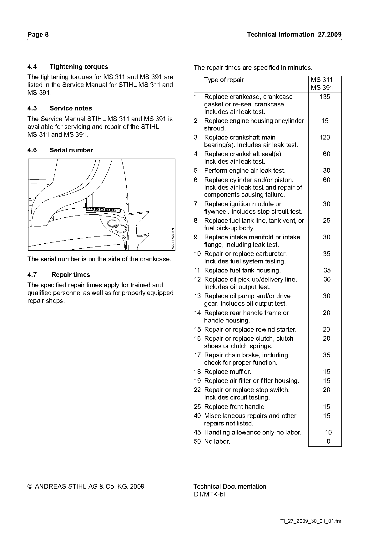
4.4      Tightening torques                                       The repair times are specified in minutes.
The tightening torques for MS 311 and MS 391 are                      Type of repair                         MS 311
listed in the Service Manual for STIHL MS 311 and                                                            MS 391
MS 391.
                                                                  1  Replace crankcase, crankcase              135
                                                                     gasket or re-seal crankcase.
4.5      Service notes
                                                                     Includes air leak test.
The Service Manual STIHL MS 311 and MS 391 is                     2 Replace engine housing or cylinder         15
available for servicing and repair of the STIHL                      shroud.
MS 311 and MS 391.                                                3 Replace crankshaft main                    120
                                                                     bearing(s). Includes air leak test.
4.6      Serial number
                                                                  4 Replace crankshaft seal(s).                 60
                                                                     Includes air leak test.
                                                                  5 Perform engine air leak test.               30
                                                                  6 Replace cylinder and/or piston.             60
                                                                     Includes air leak test and repair of
                                                                     components causing failure.
                                                                  7 Replace ignition module or                  30
                                                                     flywheel. Includes stop circuit test.
                                                                  8 Replace fuel tank line, tank vent, or       25
                                                                     fuel pick-up body.
                                                   0001TI007 KN

                                                                  9 Replace intake manifold or intake           30
                                                                     flange, including leak test.
                                                                  10 Repair or replace carburetor.              35
The serial number is on the side of the crankcase.                   Includes fuel system testing.
                                                                  11 Replace fuel tank housing.                 35
4.7      Repair times
                                                                  12 Replace oil pick-up/delivery line.         30
The specified repair times apply for trained and                     Includes oil output test.
qualified personnel as well as for properly equipped              13 Replace oil pump and/or drive              30
repair shops.                                                        gear. Includes oil output test.
                                                                  14 Replace rear handle frame or               20
                                                                     handle housing.
                                                                  15 Repair or replace rewind starter.          20
                                                                  16 Repair or replace clutch, clutch           20
                                                                     shoes or clutch springs.
                                                                  17 Repair chain brake, including              35
                                                                     check for proper function.
                                                                  18 Replace muffler.                           15
                                                                  19 Replace air filter or filter housing.      15
                                                                  22 Repair or replace stop switch.             20
                                                                     Includes circuit testing.
                                                                  25 Replace front handle                       15
                                                                  40 Miscellaneous repairs and other            15
                                                                     repairs not listed.
                                                                  45 Handling allowance only-no labor.           10
                                                                  50 No labor.                                   0

© ANDREAS STIHL AG & Co. KG, 2009                                 Technical Documentation
                                                                  D1/MTK-bl

                                                                                                 TI_27_2009_30_01_01.fm
Most of these PDFs embed fonts with a shifted character map, so the text above was recovered rather than copied — read it as a faithful but imperfect transcription, and treat the page image above each block as the authority where the two disagree — the figures exist only there, because they are vector drawings that text extraction cannot keep.