Technical Information · issue 1 of 2010
New chain saw STIHL MS 441 C-M
IssueTI 1/2010
Engine family 1138
Full text
Page 1 of 22
Text of page 1 — search, copy, screen readers
STIH)

Technical Information                                                                  01.2010

  New chain saw STIHL MS 441 C-M – Series 1138

  Contents
  1.   Functional description
  2.   Starting / stopping the engine
  3.   Specifications
  4.   Servicing accessories
  5.   Servicing

  STIHL M-Tronic
  The new STIHL MS 441 C-M chain saw expands                Electronic cold / warm start detection permits a
  the MS 441 series with the new, innovative M-Tronic       position "Start }" on the Master Control Lever™ for
  engine management system.                                 starting the chain saw. The starting procedure is
  The MS 441 C-M is the first professional STIHL            simplified requiring fewer pulls of the starter rope,
  chain saw equipped with the new, fully electronic         without switching from "choke shutter closed" to
  M-Tronic engine management system. It regulates           "starting acceleration". Good acceleration is
  the ignition timing and electronically adjusts the fuel   realized using the electronic controller. By
  flow, taking external conditions into account.            monitoring the engine temperature and speed, the
                                                            control unit continually checks the operating state of
                                                            the chain saw and adjusts the fuel flow so that
                                                            optimal engine power is always available. The
                                                            electronic memory (memory function) remembers
                                                            the settings from the last time the machine was
                                                            used. Thus if the machine is restarted under the
                                                            same general conditions, the full power of the
                                                            engine is available immediately.
                                                            According to the system of product names for
                                                            convenience features (C-versions), machines with
                                                            M-Tronic are denoted with an "M".

  TI_01_2010_30_01_02.fm                                                                       englisch / English
Page 2 of 22
Text of page 2 — search, copy, screen readers
Page 2                                                                               Technical Information 01.2010

1.       Functional description

1.1      Components


                                                                                                               4
                   2


                                                                                                        5
                                                    219TI046 KN

                                                                                                                         219TI072 KN
         1

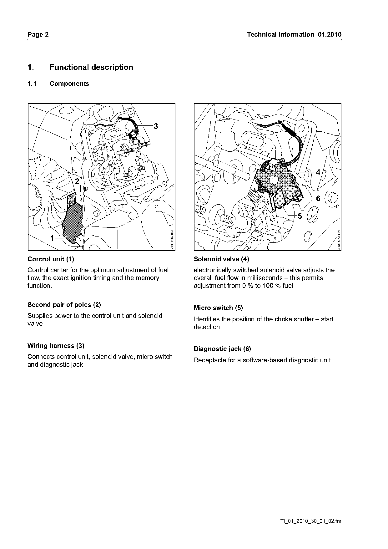
Control unit (1)                                                  Solenoid valve (4)
Control center for the optimum adjustment of fuel                 electronically switched solenoid valve adjusts the
flow, the exact ignition timing and the memory                    overall fuel flow in milliseconds – this permits
function.                                                         adjustment from 0 % to 100 % fuel

Second pair of poles (2)                                          Micro switch (5)
Supplies power to the control unit and solenoid
                                                                  Identifies the position of the choke shutter – start
valve
                                                                  detection

Wiring harness (3)                                                Diagnostic jack (6)
Connects control unit, solenoid valve, micro switch
                                                                  Receptacle for a software-based diagnostic unit
and diagnostic jack

                                                                                                  TI_01_2010_30_01_02.fm
Page 3 of 22
Text of page 3 — search, copy, screen readers
Technical Information 01.2010                                                                              Page 3

1.2     Starting                                            1.5      Full throttle
Set the Master Control Lever™ to } (Start) – choke          A regulating sequence will be initiated only if the
shutter is closed. Simultaneously, the micro switch         chain saw is operated for approx. 2 seconds under
on the switching device is closed. During starting          uniform conditions, e.g., cutting to length, at a speed
and if the engine is running, the control unit is           between 8,000 rpm and 11,200 rpm.
powered via the second pair of poles.
                                                            The solenoid valve closes for approx. 0.1 seconds –
The following processes occur within the space of           the current fuel-air mixture is made leaner.
milliseconds.
                                                            The speed change due to the brief leaning of the mix
The microprocessor detects that the micro switch            is so slight as to be imperceptible to the user.
has been actuated and thus the choke shutter is             The resulting engine speed pattern is analyzed by
closed and computes the necessary amount of fuel            the microprocessor.
and the ignition timing for the start.
During starting, the fuel-air mixture in the carburetor
is highly concentrated ("enriched") – a large quantity      The following results are possible:
of fuel flows through the solenoid valve. After initial     Engine speed increases
combustion, the quantity of fuel is reduced. The
engine does not stall out because the fuel-air              .     The mix was too rich before the solenoid valve
mixture is too rich; it keeps running and can be                  closed – the fuel flow is reduced for next phase
accelerated immediately. After the throttle trigger is            of operation
actuated, the choke shutter and micro switch open           Engine speed decreases
and the Master Control Lever™ jumps to the
                                                            .     The mix was too lean before the solenoid valve
operating position F. The control unit receives the
                                                                  closed – the fuel flow is increased for the next
information "choke shutter open" and the
                                                                  phase of operation
microprocessor adjusts the amount of fuel.
                                                            Engine speed does not change
1.3     Idle                                                .     The current carburetor setting is optimal – the
The target idle speed is controlled by adjusting the              current setting will be maintained
ignition timing and the fuel flow.
The engine speed can be influenced instantly by             1.6      Maximum speed
adjusting the ignition timing. Changing the fuel flow       The maximum permissible speed is kept constant
only influences the engine speed after 5 to                 by controling the fuel-air mixture and the ignition
10 revolutions of the crankshaft.                           timing.
For this reasons, to establish steady idling, the
ignition timing is adjusted first and then the fuel flow.
The fuel flow control is designed so that the target
idle speed is attained with the target ignition timing.

1.4     Acceleration
If the control unit detects that the engine is being
accelerated, the ignition timing is advanced and the
fuel flow is increased – the fuel-air mixture is
enriched. Optimal, spontaneous acceleration.

TI_01_2010_30_01_02.fm
Page 4 of 22
Text of page 4 — search, copy, screen readers
Page 4                                                                        Technical Information 01.2010

1.7      Advantages                                       2.      Starting / stopping the engine
Easy starting –
                                                          2.1     Positions of the Master Control Lever™
With M-Tronic there is only one start position on the
Master Control Lever™ because the system detects
cold or warm starts and electronically computes the
exact fuel flow allowing starting with a few pulls of                                    STOP
the starter rope and immediate full throttle.

Constant optimum engine performance –
                                                                               0
By monitoring of the engine temperature and speed,
the control unit continually checks the operating
state of the chain saw and adjusts the fuel flow for

                                                                                                                219TI067 KN
constant optimum engine performance.

Very good acceleration –
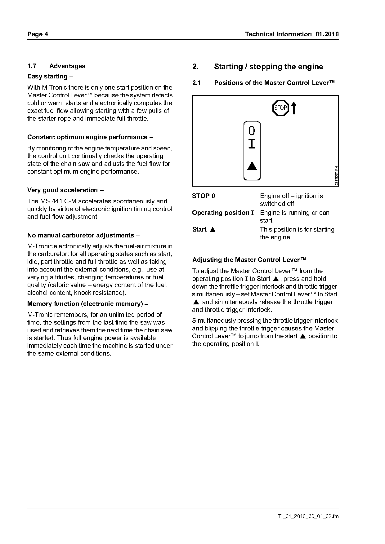
                                                          STOP 0               Engine off – ignition is
The MS 441 C-M accelerates spontaneously and                                   switched off
quickly by virtue of electronic ignition timing control
                                                          Operating position F Engine is running or can
and fuel flow adjustment.
                                                                               start
                                                          Start }              This position is for starting
No manual carburetor adjustments –                                             the engine
M-Tronic electronically adjusts the fuel-air mixture in
the carburetor: for all operating states such as start,
idle, part throttle and full throttle as well as taking   Adjusting the Master Control Lever™
into account the external conditions, e.g., use at        To adjust the Master Control Lever™ from the
varying altitudes, changing temperatures or fuel          operating position F to Start }, press and hold
quality (caloric value – energy content of the fuel,      down the throttle trigger interlock and throttle trigger
alcohol content, knock resistance).                       simultaneously – set Master Control Lever™ to Start
Memory function (electronic memory) –                     } and simultaneously release the throttle trigger
                                                          and throttle trigger interlock.
M-Tronic remembers, for an unlimited period of
time, the settings from the last time the saw was         Simultaneously pressing the throttle trigger interlock
used and retrieves them the next time the chain saw       and blipping the throttle trigger causes the Master
is started. Thus full engine power is available           Control Lever™ to jump from the start } position to
immediately each time the machine is started under        the operating position F.
the same external conditions.

                                                                                           TI_01_2010_30_01_02.fm
Page 5 of 22
Text of page 5 — search, copy, screen readers
Technical Information 01.2010                                                                                         Page 5

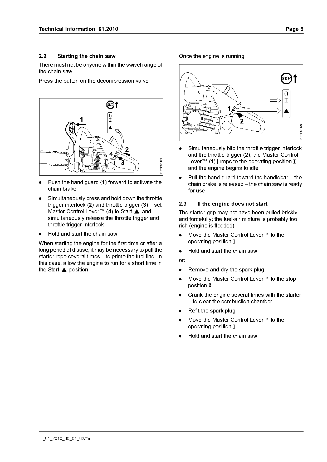
2.2       Starting the chain saw                                      Once the engine is running
There must not be anyone within the swivel range of
the chain saw.
Press the button on the decompression valve

                                                                                             1
                    1                                                                              2

                                                                                                                             219TI068 KN
                                           2                          .     Simultaneously blip the throttle trigger interlock
                                 4                                          and the throttle trigger (2); the Master Control
                                                        219TI068 KN
                                       3                                    Lever™ (1) jumps to the operating position F
                                                                            and the engine begins to idle
                                                                      .     Pull the hand guard toward the handlebar – the
.     Push the hand guard (1) forward to activate the                       chain brake is released – the chain saw is ready
      chain brake                                                           for use
.     Simultaneously press and hold down the throttle
      trigger interlock (2) and throttle trigger (3) – set            2.3       If the engine does not start
      Master Control Lever™ (4) to Start } and                        The starter grip may not have been pulled briskly
      simultaneously release the throttle trigger and                 and forcefully; the fuel-air mixture is probably too
      throttle trigger interlock                                      rich (engine is flooded).
.     Hold and start the chain saw                                    .     Move the Master Control Lever™ to the
When starting the engine for the first time or after a                      operating position F
long period of disuse, it may be necessary to pull the                .     Hold and start the chain saw
starter rope several times – to prime the fuel line. In
this case, allow the engine to run for a short time in                or:
the Start } position.                                                 .     Remove and dry the spark plug
                                                                      .     Move the Master Control Lever™ to the stop
                                                                            position 0
                                                                      .     Crank the engine several times with the starter
                                                                            – to clear the combustion chamber
                                                                      .     Refit the spark plug
                                                                      .     Move the Master Control Lever™ to the
                                                                            operating position F
                                                                      .     Hold and start the chain saw

TI_01_2010_30_01_02.fm
Page 6 of 22
Text of page 6 — search, copy, screen readers
Page 6                                                                                  Technical Information 01.2010

3.       Specifications                                              5.      Servicing
Engine                                                               The specific national safety regulations and the
                                                                     safety instructions in the instruction manual must be
STIHL single cylinder two-                                           observed if the machine has to be started up during
stroke engine                                                        servicing.
Displacement:                     4.31 cu.in.
                                  70.7 cm3                           5.1     Troubleshooting plan
Engine power to ISO 8893:         5.6 hp 4.2 kW                      The flow charts that follow deal with specific parts
                                  at 9,500 rpm                       diagnosis and troubleshooting for the M-Tronic
Idle speed:                       2,800 rpm                          engine management system.
High speed setting when           13,500 rpm                         The flow charts help you to take the correct step at
performing repairs (with bar                                         the correct time.
and chain):
                                                                     All other diagnosis and repair operations remain
Weight:
                                                                     unchanged.
 – MS 441 C-M                     14.6 lbs. (6.6 kg)

4.       Servicing accessories

4.1      New special tool
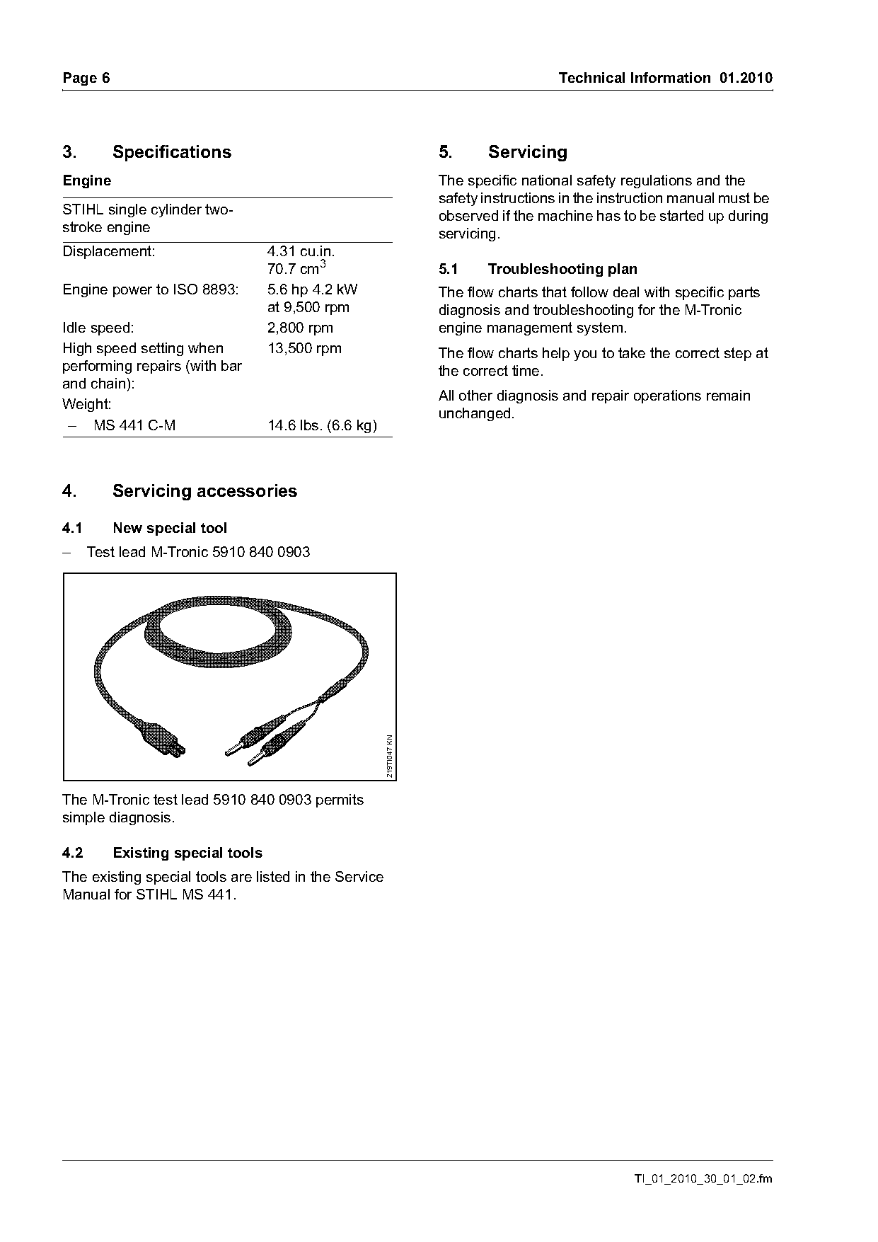
–     Test lead M-Tronic 5910 840 0903
                                                       219TI047 KN

The M-Tronic test lead 5910 840 0903 permits
simple diagnosis.

4.2      Existing special tools
The existing special tools are listed in the Service
Manual for STIHL MS 441.

                                                                                                    TI_01_2010_30_01_02.fm
Page 7 of 22
Text of page 7 — search, copy, screen readers
Technical Information 01.2010                                                                                                    Page 7

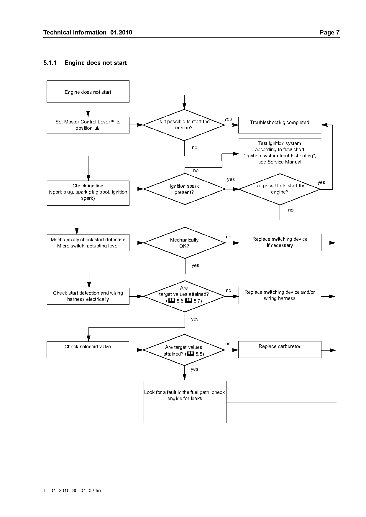
5.1.1    Engine does not start

         Engine does not start

                                                                                  yes
     Set Master Control Lever™ to                 Is it possible to start the                  Troubleshooting completed
             position }                                    engine?

                                                                                                    Test ignition system
                                                                   no                              according to flow chart
                                                                                            "Ignition system troubleshooting“,
                                                                                                    see Service Manual
                                                                                      yes
                                                                                                                                 yes
             Check ignition                             Ignition spark                          Is it possible to start the
  (spark plug, spark plug boot, ignition                  present?                                       engine?
                 spark)

  Mechanically check start detection                    Mechanically                            Replace switching device
    Micro switch, actuating lever                          OK?                                        if necessary

                                                                   yes

                                                            Are                       no
    Check start detection and wiring              target values attained?                   Replace switching device and/or
         harness electrically                                                                       wiring harness
                                                     (b 5.6,b 5.7)

                                                                   yes

         Check solenoid valve                        Are target values                             Replace carburetor
                                                    attained? (b 5.5)

                                                                   yes

                                           Look for a fault in the fuel path, check
                                                      engine for leaks

TI_01_2010_30_01_02.fm
Page 8 of 22
Text of page 8 — search, copy, screen readers
Page 8                                                                                  Technical Information 01.2010

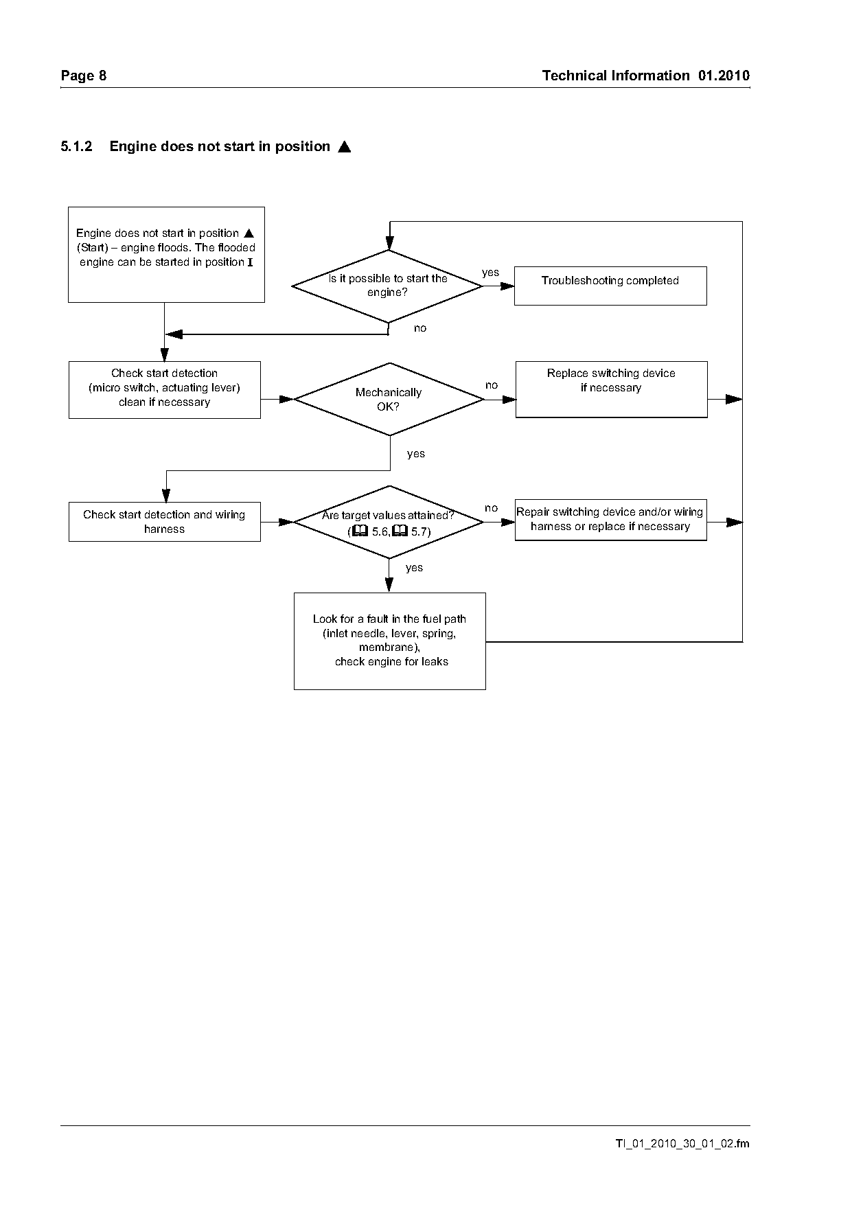
5.1.2    Engine does not start in position }

  Engine does not start in position }
  (Start) – engine floods. The flooded
   engine can be started in position F
                                                                             yes
                                            Is it possible to start the                 Troubleshooting completed
                                                     engine?

        Check start detection                                                            Replace switching device
    (micro switch, actuating lever)                                          no                if necessary
                                                  Mechanically
          clean if necessary                         OK?

                                                             yes

                                                                             no    Repair switching device and/or wiring
   Check start detection and wiring       Are target values attained?
               harness                         (b 5.6,b 5.7)                         harness or replace if necessary

                                                             yes

                                         Look for a fault in the fuel path
                                           (inlet needle, lever, spring,
                                                   membrane),
                                              check engine for leaks

                                                                                                      TI_01_2010_30_01_02.fm
Page 9 of 22
Text of page 9 — search, copy, screen readers
Technical Information 01.2010                                                                                              Page 9

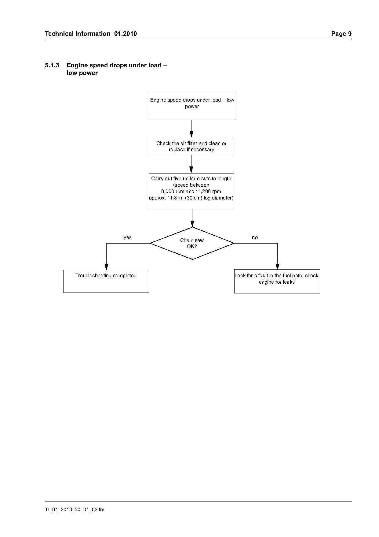
5.1.3   Engine speed drops under load –
        low power

                                       Engine speed drops under load – low
                                                     power

                                          Check the air filter and clean or
                                              replace if necessary

                                        Carry out five uniform cuts to length
                                                  (speed between
                                            8,000 rpm and 11,200 rpm
                                       approx. 11.8 in. (30 cm) log diameter)

                              yes                                                       no
                                                     Chain saw
                                                       OK?

           Troubleshooting completed                                            Look for a fault in the fuel path, check
                                                                                           engine for leaks

TI_01_2010_30_01_02.fm
Page 10 of 22
Text of page 10 — search, copy, screen readers
Page 10                                                                                Technical Information 01.2010

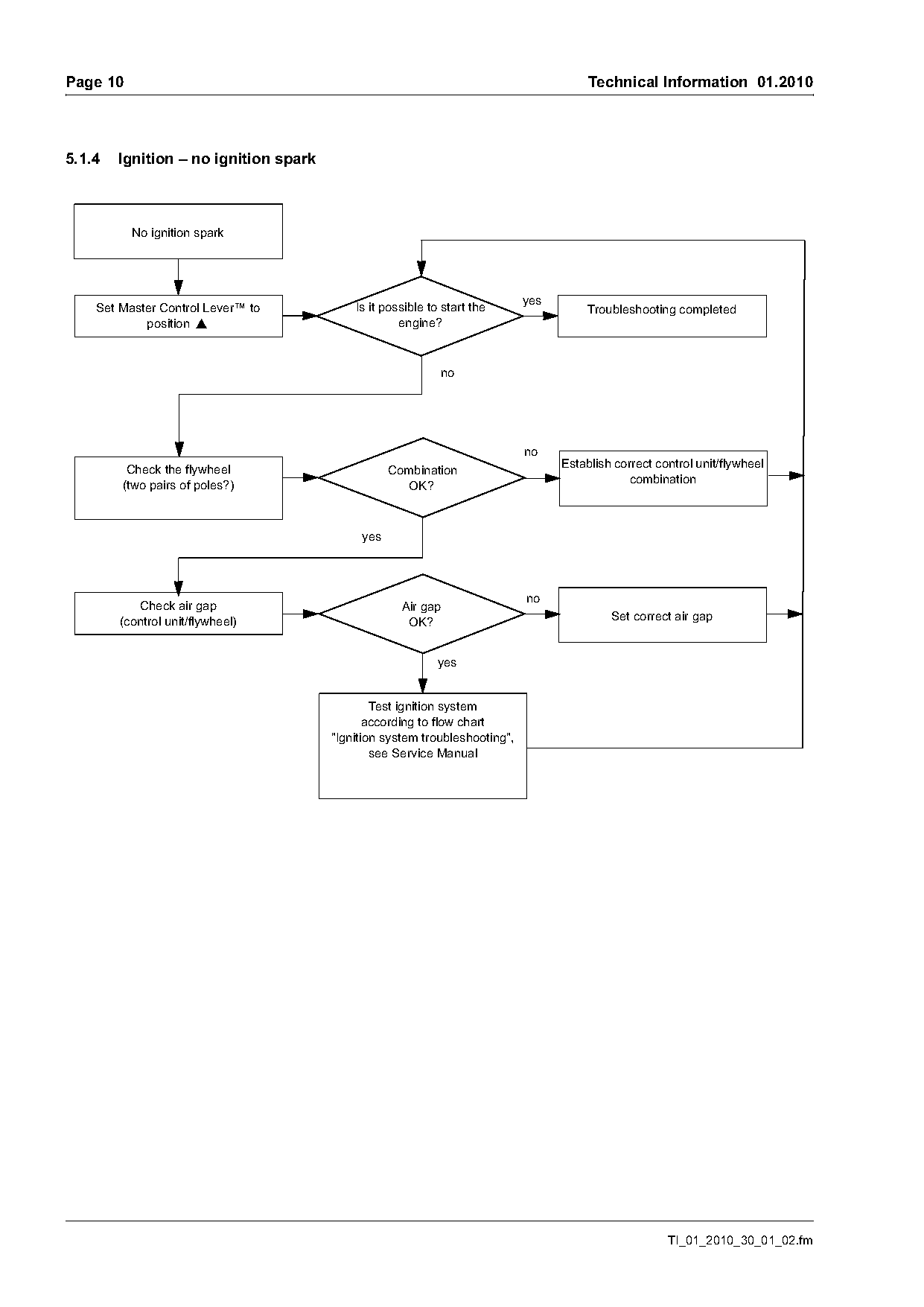
5.1.4   Ignition – no ignition spark

          No ignition spark

                                                                            yes
    Set Master Control Lever™ to           Is it possible to start the                 Troubleshooting completed
            position }                              engine?

         Check the flywheel                                                       Establish correct control unit/flywheel
                                                  Combination
        (two pairs of poles?)                                                                  combination
                                                    OK?

                                            yes

           Check air gap                            Air gap
        (control unit/flywheel)                      OK?                                   Set correct air gap

                                                            yes

                                               Test ignition system
                                              according to flow chart
                                       "Ignition system troubleshooting",
                                               see Service Manual

                                                                                                      TI_01_2010_30_01_02.fm
Page 11 of 22
Text of page 11 — search, copy, screen readers
Technical Information 01.2010                                                                                 Page 11

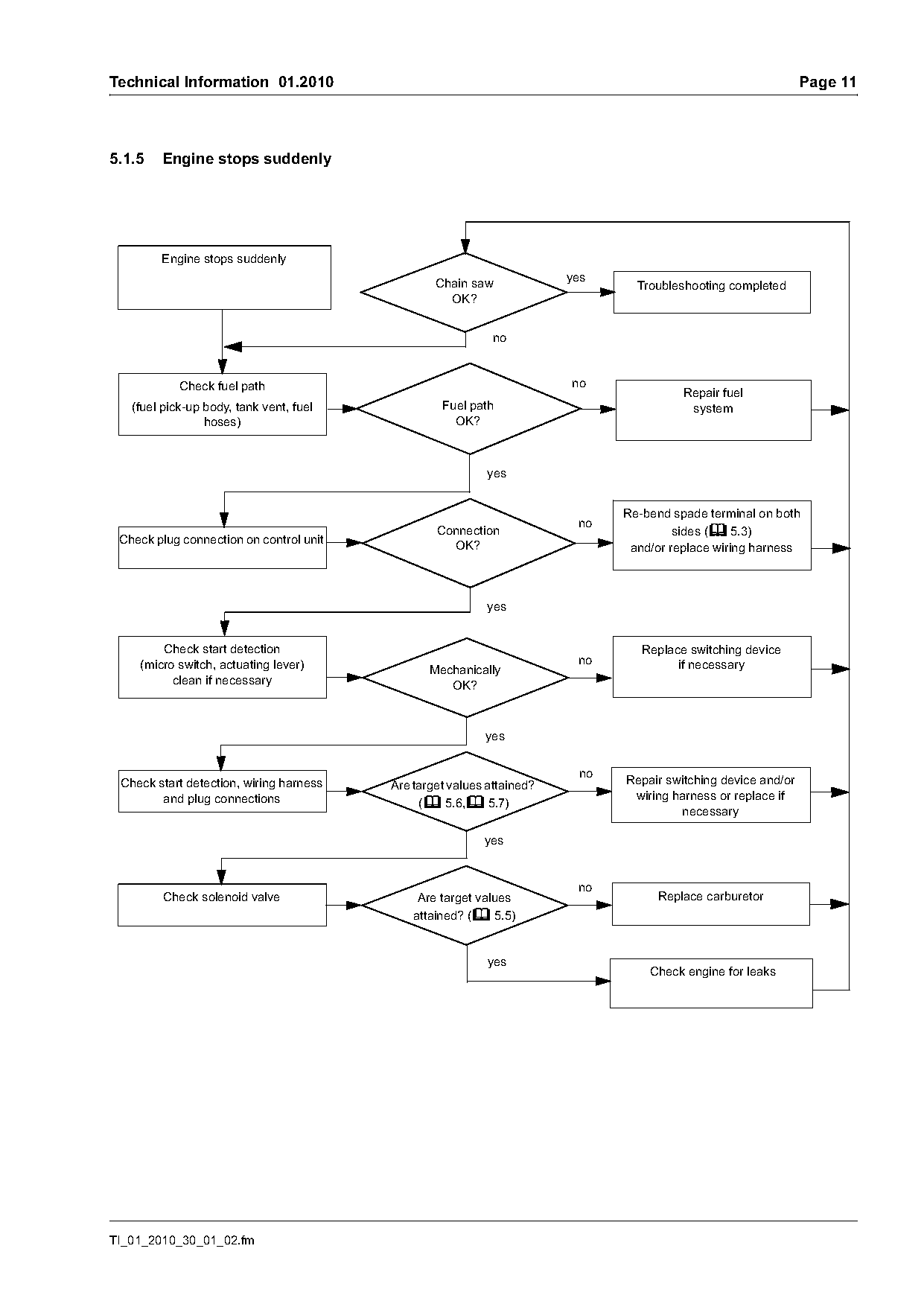
5.1.5   Engine stops suddenly

        Engine stops suddenly
                                                                       yes
                                                 Chain saw                     Troubleshooting completed
                                                   OK?

            Check fuel path                                            no
                                                                                       Repair fuel
   (fuel pick-up body, tank vent, fuel            Fuel path                             system
                 hoses)                             OK?

                                                           yes

                                                                             Re-bend spade terminal on both
                                                 Connection                           sides (b 5.3)
 Check plug connection on control unit             OK?                        and/or replace wiring harness

                                                           yes

        Check start detection                                                   Replace switching device
    (micro switch, actuating lever)                                     no            if necessary
                                                Mechanically
          clean if necessary                       OK?

                                                          yes

 Check start detection, wiring harness   Are target values attained?         Repair switching device and/or
        and plug connections                                                  wiring harness or replace if
                                              (b 5.6,b 5.7)
                                                                                      necessary

                                                          yes

         Check solenoid valve                 Are target values                   Replace carburetor
                                             attained? (b 5.5)

                                                           yes
                                                                                 Check engine for leaks

TI_01_2010_30_01_02.fm
Page 12 of 22
Text of page 12 — search, copy, screen readers
Page 12                                                                                 Technical Information 01.2010

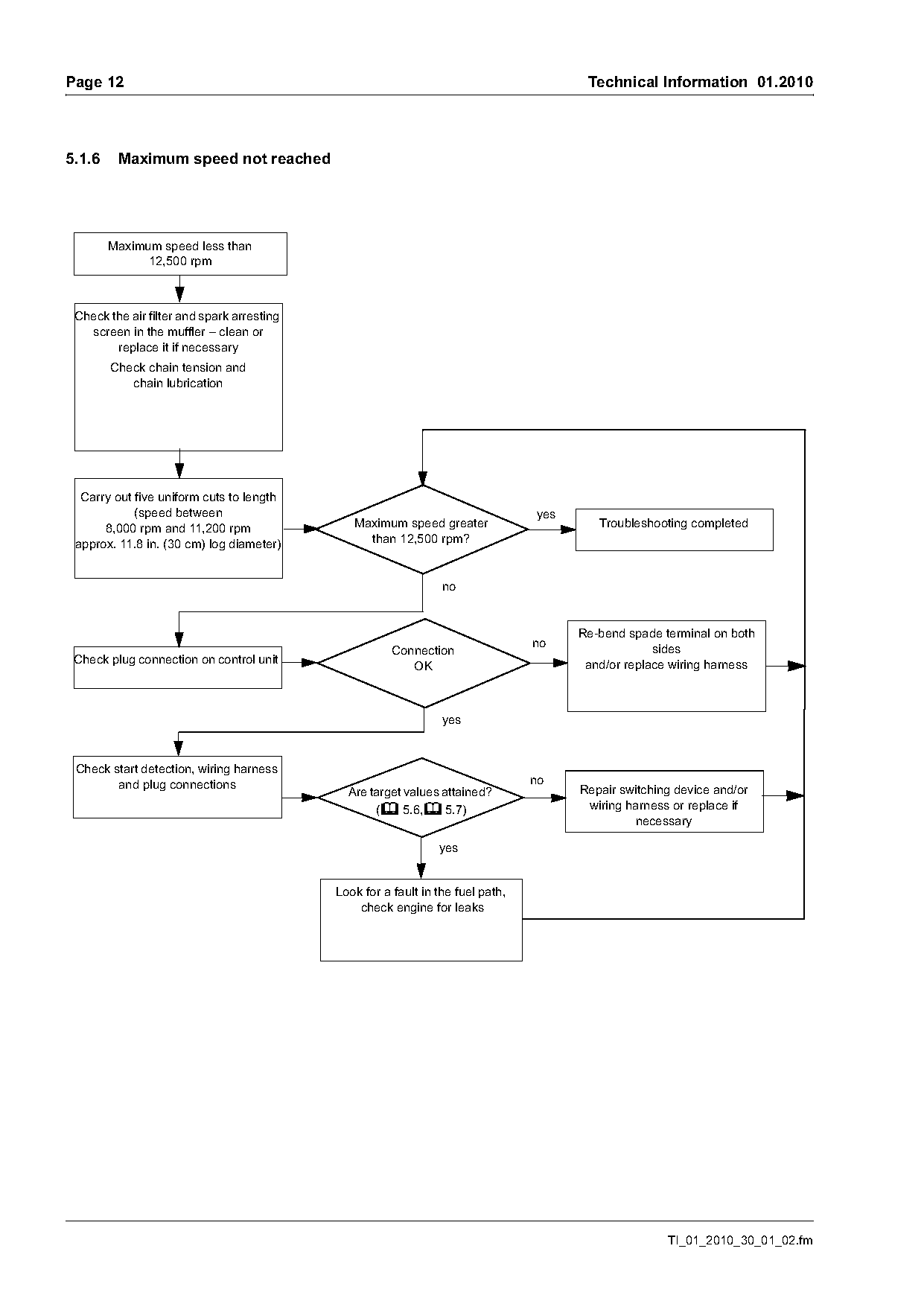
5.1.6    Maximum speed not reached

        Maximum speed less than
              12,500 rpm

 Check the air filter and spark arresting
   screen in the muffler – clean or
        replace it if necessary
        Check chain tension and
           chain lubrication

  Carry out five uniform cuts to length
            (speed between                                                       yes
      8,000 rpm and 11,200 rpm                 Maximum speed greater                      Troubleshooting completed
 approx. 11.8 in. (30 cm) log diameter)          than 12,500 rpm?

                                                                                       Re-bend spade terminal on both
                                                                                 no                 sides
                                                       Connection
 Check plug connection on control unit                    OK                            and/or replace wiring harness

                                                                 yes

 Check start detection, wiring harness
        and plug connections                                                     no
                                              Are target values attained?              Repair switching device and/or
                                                   (b 5.6,b 5.7)                        wiring harness or replace if
                                                                                                necessary

                                                                yes

                                            Look for a fault in the fuel path,
                                                check engine for leaks

                                                                                                      TI_01_2010_30_01_02.fm
Page 13 of 22
Text of page 13 — search, copy, screen readers
Technical Information 01.2010                                                                                    Page 13

5.2       Ohmmeter and plug connections
An ohmmeter (multimeter) with a diode tester is
required for the following test procedures.
To ensure a reliable contact:
–     Use appropriate test probes
–     Do not widen or bend plugs and connector tags
–     Unplug and plug in plug connections by hand
      whenever possible in the direction of the

                                                                                                                        219TI075 KN
      connector tags – do not insert them on a slant or
      tilt or widen them
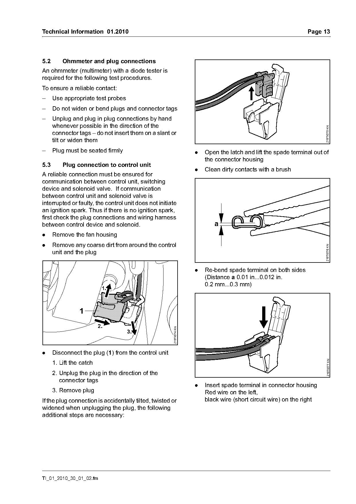
–     Plug must be seated firmly                                     .   Open the latch and lift the spade terminal out of
                                                                         the connector housing
5.3       Plug connection to control unit
                                                                     .   Clean dirty contacts with a brush
A reliable connection must be ensured for
communication between control unit, switching
device and solenoid valve. If communication
between control unit and solenoid valve is
interrupted or faulty, the control unit does not initiate
an ignition spark. Thus if there is no ignition spark,
first check the plug connections and wiring harness
between control device and solenoid.                                        a
.     Remove the fan housing
.     Remove any coarse dirt from around the control

                                                                                                                        219TI076 KN
      unit and the plug

                                                                     .   Re-bend spade terminal on both sides
                                                                         (Distance a 0.01 in...0.012 in.
                                                                         0.2 mm...0.3 mm)
                           1.

                 1
                          2.
                                                       219TI074 KN

                                    3.

.     Disconnect the plug (1) from the control unit
                                                                                                                         219TI077 KN

      1. Lift the catch
      2. Unplug the plug in the direction of the
         connector tags
                                                                     .   Insert spade terminal in connector housing
      3. Remove plug                                                     Red wire on the left,
If the plug connection is accidentally tilted, twisted or                black wire (short circuit wire) on the right
widened when unplugging the plug, the following
additional steps are necessary:

TI_01_2010_30_01_02.fm
Page 14 of 22
Text of page 14 — search, copy, screen readers
Page 14                                                                                Technical Information 01.2010

                                                                   5.4      Connecting the M-Tronic test lead to the
                                                                            diagnostic jack

          2
          1

                                                     219TI078 KN
                                                                                                             2
                                                                                1

                                                                                                                        219TI048 KN
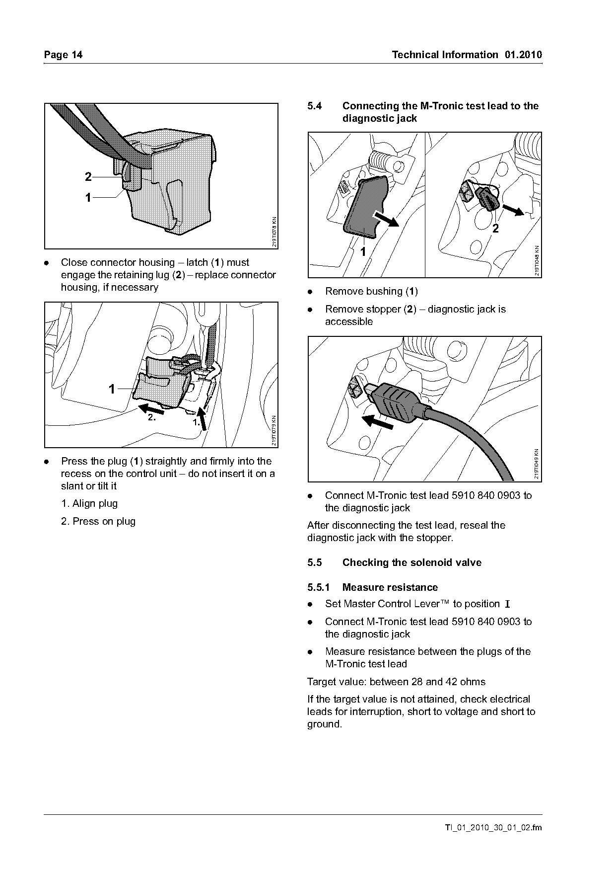
.   Close connector housing – latch (1) must
    engage the retaining lug (2) – replace connector
    housing, if necessary                                          .     Remove bushing (1)
                                                                   .     Remove stopper (2) – diagnostic jack is
                                                                         accessible


                        2.
                                                    219TI079 KN

                                  1.

                                                                                                                       219TI049 KN
.   Press the plug (1) straightly and firmly into the
    recess on the control unit – do not insert it on a
    slant or tilt it
                                                                   .     Connect M-Tronic test lead 5910 840 0903 to
    1. Align plug                                                        the diagnostic jack
    2. Press on plug                                               After disconnecting the test lead, reseal the
                                                                   diagnostic jack with the stopper.

                                                                   5.5      Checking the solenoid valve

                                                                   5.5.1    Measure resistance
                                                                   .     Set Master Control Lever™ to position F
                                                                   .     Connect M-Tronic test lead 5910 840 0903 to
                                                                         the diagnostic jack
                                                                   .     Measure resistance between the plugs of the
                                                                         M-Tronic test lead
                                                                   Target value: between 28 and 42 ohms
                                                                   If the target value is not attained, check electrical
                                                                   leads for interruption, short to voltage and short to
                                                                   ground.

                                                                                                  TI_01_2010_30_01_02.fm
Page 15 of 22
Text of page 15 — search, copy, screen readers
Technical Information 01.2010                                                                                         Page 15

5.5.2     Checking the switching function
.     Set Master Control Lever™ to position STOP 0
.     Connect M-Tronic test lead 5910 840 0903 to
      the diagnostic jack
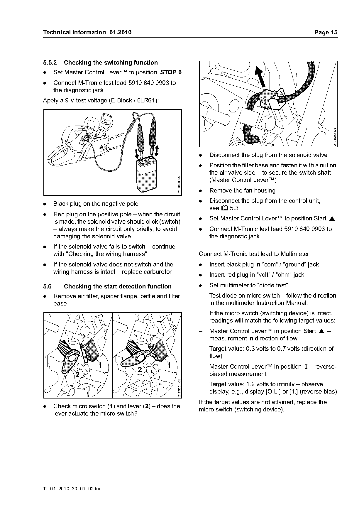
Apply a 9 V test voltage (E-Block / 6LR61):

                                                                                                                             219TI052 KN
                                                                       .   Disconnect the plug from the solenoid valve
                                                                       .   Position the filter base and fasten it with a nut on
                                                                           the air valve side – to secure the switch shaft
                                                         219TI050 KN
                                                                           (Master Control Lever™)
                                                                       .   Remove the fan housing

.     Black plug on the negative pole                                  .   Disconnect the plug from the control unit,
                                                                           see b 5.3
.     Red plug on the positive pole – when the circuit
                                                                       .   Set Master Control Lever™ to position Start }
      is made, the solenoid valve should click (switch)
      – always make the circuit only briefly, to avoid                 .   Connect M-Tronic test lead 5910 840 0903 to
      damaging the solenoid valve                                          the diagnostic jack
.     If the solenoid valve fails to switch – continue
      with "Checking the wiring harness"                               Connect M-Tronic test lead to Multimeter:
.     If the solenoid valve does not switch and the                    .   Insert black plug in "com" / "ground" jack
      wiring harness is intact – replace carburetor                    .   Insert red plug in "volt" / "ohm" jack
5.6       Checking the start detection function                        .   Set multimeter to "diode test"
.     Remove air filter, spacer flange, baffle and filter                  Test diode on micro switch – follow the direction
      base                                                                 in the multimeter Instruction Manual:
                                                                           If the micro switch (switching device) is intact,
                                                                           readings will match the following target values:
                                                                       –   Master Control Lever™ in position Start } –
                                                                           measurement in direction of flow
                                                                           Target value: 0.3 volts to 0.7 volts (direction of
                                                                           flow)
                        1                          1                   –   Master Control Lever™ in position F – reverse-
                                       2
              2                                                            biased measurement
                                                         219TI051 KN

                                                                           Target value: 1.2 volts to infinity – observe
                                                                           display, e.g., display [O.L.] or [1.] (reverse bias)
                                                                       If the target values are not attained, replace the
.     Check micro switch (1) and lever (2) – does the
                                                                       micro switch (switching device).
      lever actuate the micro switch?

TI_01_2010_30_01_02.fm
Page 16 of 22
Text of page 16 — search, copy, screen readers
Page 16                                                                                  Technical Information 01.2010

5.7      Checking the wiring harness
.     Remove the fan housing
.     Remove air filter and spacer flange                               6
.     Set Master Control Lever™ to position STOP 0
.     Disconnect the plug from the control unit,
      see b 5.3

                                                                                                                         219TI080 KN
                                                                                                      3

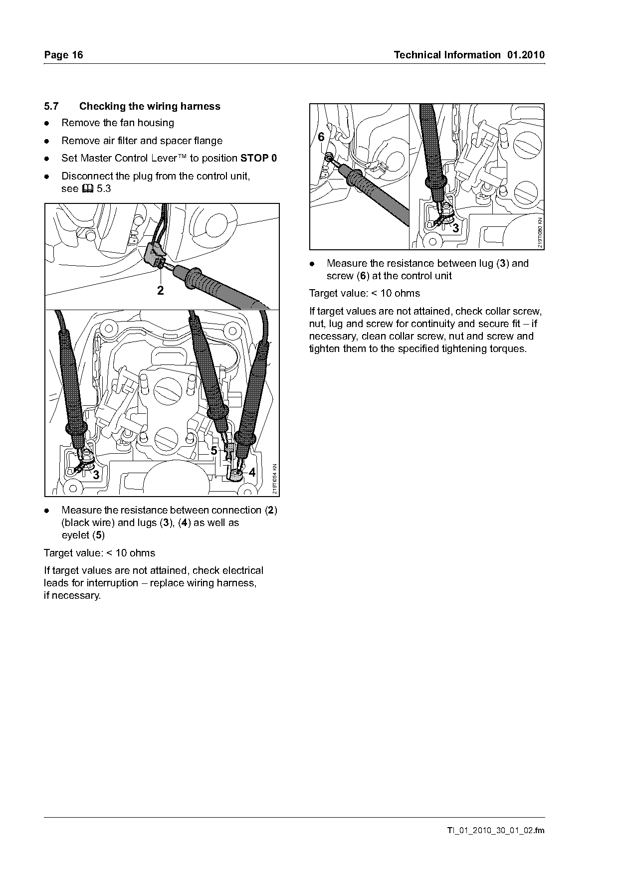
                                                                    .       Measure the resistance between lug (3) and
                                                                            screw (6) at the control unit
                           2                                        Target value: < 10 ohms
                                                                    If target values are not attained, check collar screw,
                                                                    nut, lug and screw for continuity and secure fit – if
                                                                    necessary, clean collar screw, nut and screw and
                                                                    tighten them to the specified tightening torques.

                                       5
                                                      219TI054 KN

            3                                  4

.     Measure the resistance between connection (2)
      (black wire) and lugs (3), (4) as well as
      eyelet (5)
Target value: < 10 ohms
If target values are not attained, check electrical
leads for interruption – replace wiring harness,
if necessary.

                                                                                                    TI_01_2010_30_01_02.fm
Page 17 of 22
Text of page 17 — search, copy, screen readers
Technical Information 01.2010                                                                                        Page 17

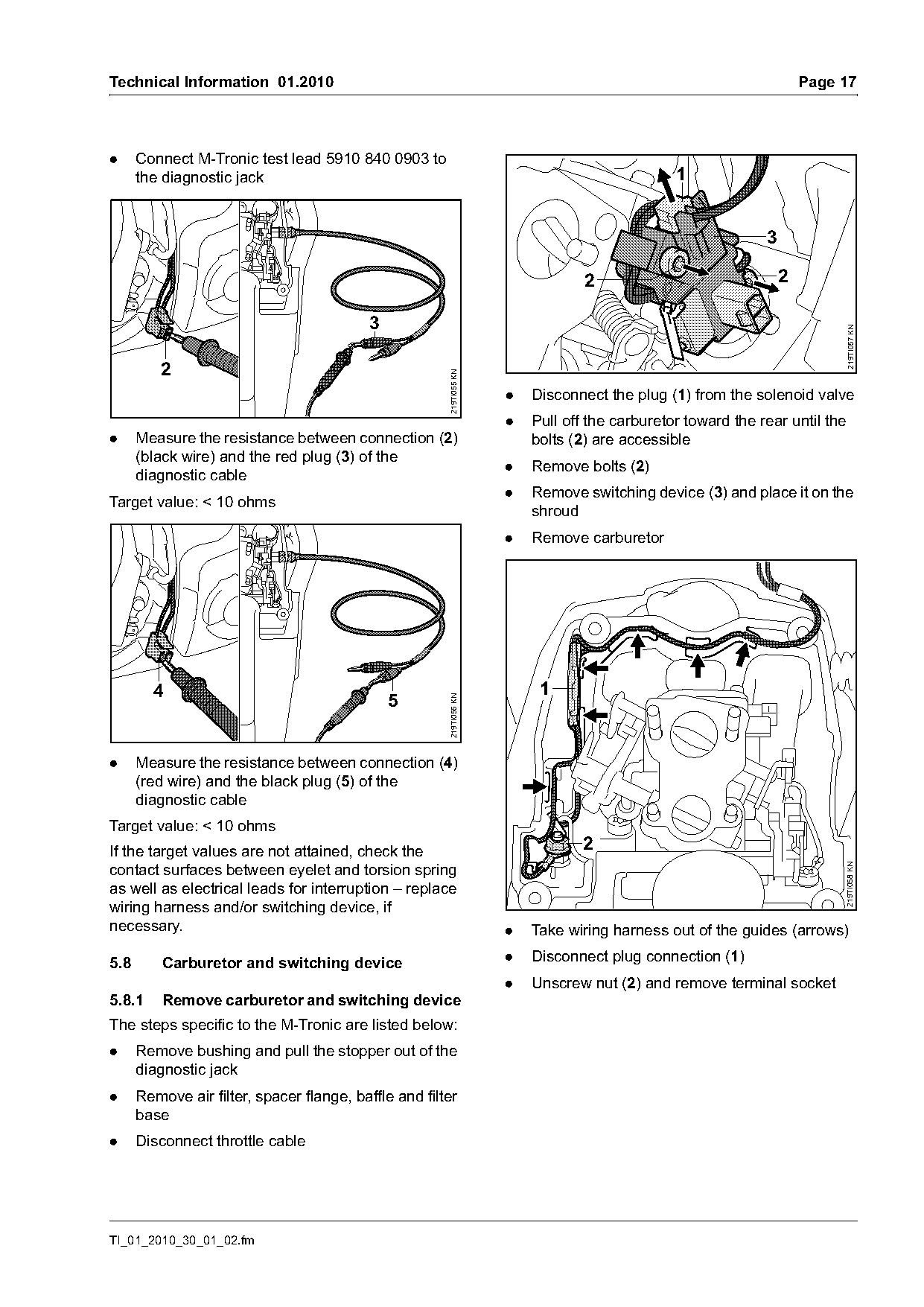
.     Connect M-Tronic test lead 5910 840 0903 to
      the diagnostic jack                                                                      1


                                                                                 2                               2


                                                                                                                          219TI057 KN
         2

                                                       219TI055 KN
                                                                     .   Disconnect the plug (1) from the solenoid valve
                                                                     .   Pull off the carburetor toward the rear until the
.     Measure the resistance between connection (2)                      bolts (2) are accessible
      (black wire) and the red plug (3) of the
                                                                     .   Remove bolts (2)
      diagnostic cable
                                                                     .   Remove switching device (3) and place it on the
Target value: < 10 ohms
                                                                         shroud
                                                                     .   Remove carburetor

        4                                                                 1
                                               5
                                                       219TI056 KN

.     Measure the resistance between connection (4)
      (red wire) and the black plug (5) of the
      diagnostic cable
Target value: < 10 ohms
If the target values are not attained, check the                                2
contact surfaces between eyelet and torsion spring
                                                                                                                          219TI058 KN

as well as electrical leads for interruption – replace
wiring harness and/or switching device, if
necessary.                                                           .   Take wiring harness out of the guides (arrows)

5.8       Carburetor and switching device                            .   Disconnect plug connection (1)
                                                                     .   Unscrew nut (2) and remove terminal socket
5.8.1     Remove carburetor and switching device
The steps specific to the M-Tronic are listed below:
.     Remove bushing and pull the stopper out of the
      diagnostic jack
.     Remove air filter, spacer flange, baffle and filter
      base
.     Disconnect throttle cable

TI_01_2010_30_01_02.fm
Page 18 of 22
Text of page 18 — search, copy, screen readers
Page 18                                                                             Technical Information 01.2010

5.8.2   Carburetor service work
Service work on metering diaphragm, pump
diaphragm, inlet needle, lever, gaskets, choke                                                         3
shutter and air valve housing same as standard MS
441 carburetor.
                                                                                     4                     1
                                                                                              4
                                                                      5
                                     2                                                                           2

                                 1
                                                   219TI059 KN

                                                                                                                        219TI081 KN
                                                                          7     6
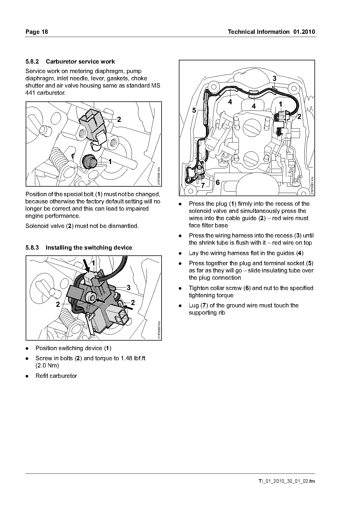
Position of the special bolt (1) must not be changed,
because otherwise the factory default setting will no            .   Press the plug (1) firmly into the recess of the
longer be correct and this can lead to impaired                      solenoid valve and simultaneously press the
engine performance.                                                  wires into the cable guide (2) – red wire must
Solenoid valve (2) must not be dismantled.                           face filter base
                                                                 .   Press the wiring harness into the recess (3) until
                                                                     the shrink tube is flush with it – red wire on top
5.8.3   Installing the switching device
                                                                 .   Lay the wiring harness flat in the guides (4)
                          1                                      .   Press together the plug and terminal socket (5)
                                                                     as far as they will go – slide insulating tube over
                                                                     the plug connection
                                         3                       .   Tighten collar screw (6) and nut to the specified
                                                                     tightening torque
            2                                2                   .   Lug (7) of the ground wire must touch the
                                                                     supporting rib
                                                   219TI060 KN

.   Position switching device (1)
.   Screw in bolts (2) and torque to 1.48 lbf.ft
    (2.0 Nm)
.   Refit carburetor

                                                                                                  TI_01_2010_30_01_02.fm
Page 19 of 22
Text of page 19 — search, copy, screen readers
Technical Information 01.2010                                                                                    Page 19

5.9       Wiring harness

5.9.1     Removing the wiring harness
.     Remove the fan housing
.     Remove air filter, spacer flange, baffle and filter
      base
.     Unplug the spark plug boot


                                                                                                                          219TI064 KN
                         1
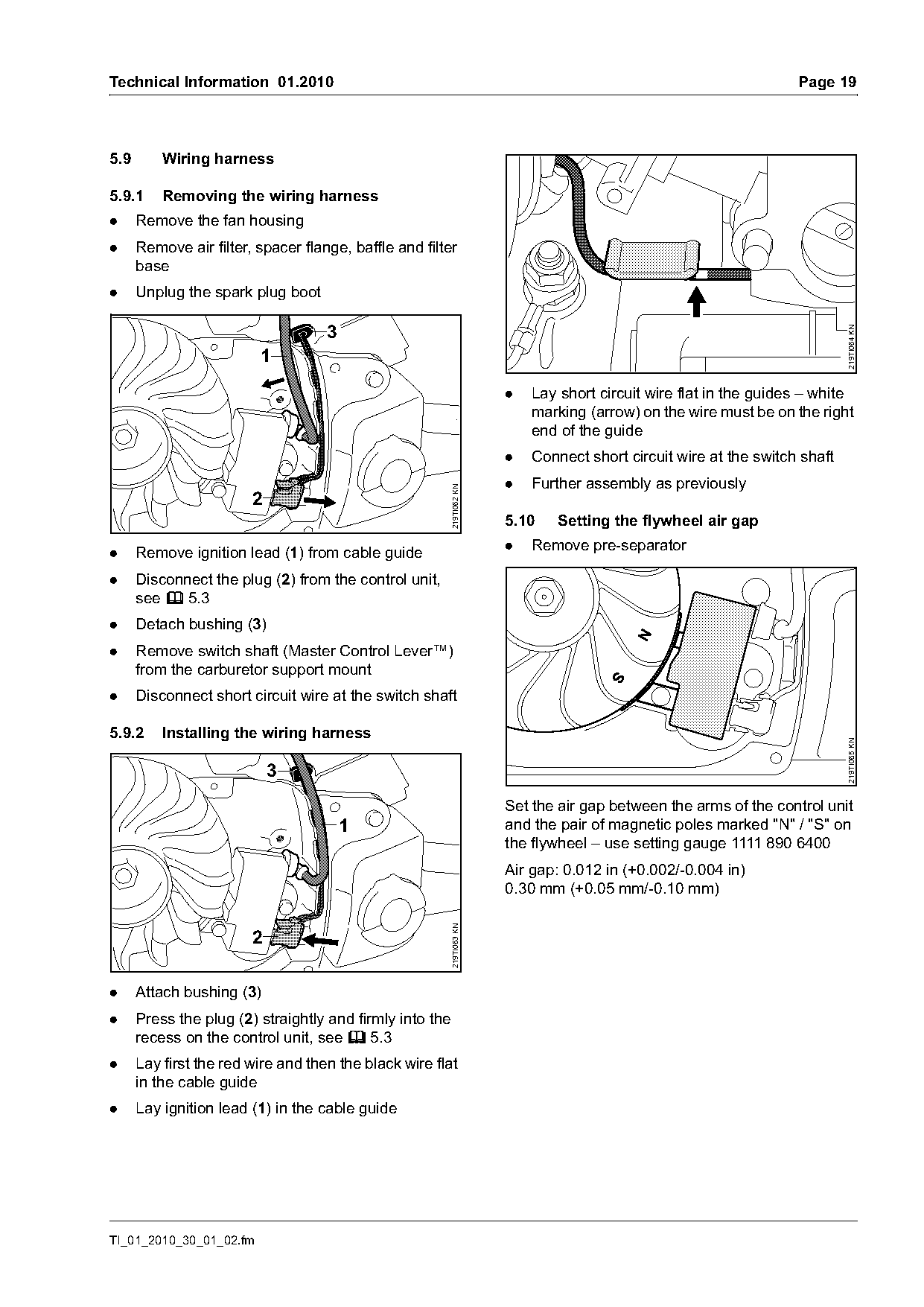
                                                                     .   Lay short circuit wire flat in the guides – white
                                                                         marking (arrow) on the wire must be on the right
                                                                         end of the guide
                                                                     .   Connect short circuit wire at the switch shaft
                                                                     .   Further assembly as previously
                                                       219TI062 KN

                        2
                                                                     5.10    Setting the flywheel air gap
                                                                     .   Remove pre-separator
.     Remove ignition lead (1) from cable guide
.     Disconnect the plug (2) from the control unit,
      see b 5.3
.     Detach bushing (3)
.     Remove switch shaft (Master Control Lever™)
      from the carburetor support mount
.     Disconnect short circuit wire at the switch shaft

5.9.2     Installing the wiring harness

                                                                                                                          219TI065 KN
                            3
                                                                     Set the air gap between the arms of the control unit
                                        1                            and the pair of magnetic poles marked "N" / "S" on
                                                                     the flywheel – use setting gauge 1111 890 6400
                                                                     Air gap: 0.012 in (+0.002/-0.004 in)
                                                                     0.30 mm (+0.05 mm/-0.10 mm)
                                                       219TI063 KN


.     Attach bushing (3)
.     Press the plug (2) straightly and firmly into the
      recess on the control unit, see b 5.3
.     Lay first the red wire and then the black wire flat
      in the cable guide
.     Lay ignition lead (1) in the cable guide

TI_01_2010_30_01_02.fm
Page 20 of 22
Text of page 20 — search, copy, screen readers
Page 20                                                  Technical Information 01.2010

5.11    Calibrating the control unit
If the control unit or carburetor is replaced during
servicing, the M-Tronic must be calibrated.
.   Remove the saw chain and guide bar
.   Install chain sprocket cover
.   Set Master Control Lever™ to Start }
.   Start chain saw – do not blip the throttle trigger
.   Let the engine run for at least 60 seconds in the
    start position and then move the Master Control
    Lever™ from the position Start } to STOP 0 –
    calibration is finished
The control unit is adjusted to the carburetor while
the engine runs in the position Start }. The engine
must be switched off immediately for the information
to be stored in the control unit.

5.12    Muffler, plugs
Do not refit used plugs; push new plugs straight in
with a blunt tool – do not damage plugs.

                                                                   TI_01_2010_30_01_02.fm
Page 21 of 22
Text of page 21 — search, copy, screen readers
Technical Information 01.2010                                                                         Page 21

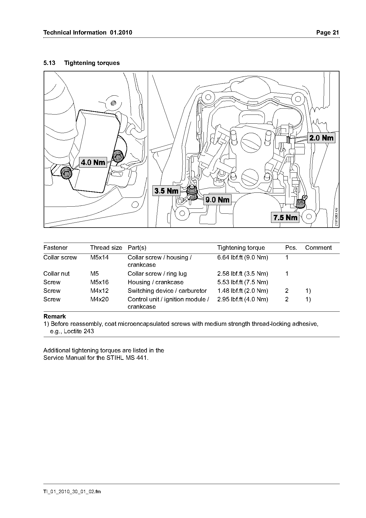
5.13    Tightening torques

                                                                                                           219TI083 KN
Fastener          Thread size Part(s)                              Tightening torque      Pcs.   Comment
Collar screw      M5x14         Collar screw / housing /           6.64 lbf.ft (9.0 Nm)   1
                                crankcase
Collar nut        M5            Collar screw / ring lug            2.58 lbf.ft (3.5 Nm)   1
Screw             M5x16         Housing / crankcase                5.53 lbf.ft (7.5 Nm)
Screw             M4x12         Switching device / carburetor      1.48 lbf.ft (2.0 Nm)   2      1)
Screw             M4x20         Control unit / ignition module /   2.95 lbf.ft (4.0 Nm)   2      1)
                                crankcase
Remark
1) Before reassembly, coat microencapsulated screws with medium strength thread-locking adhesive,
   e.g., Loctite 243

Additional tightening torques are listed in the
Service Manual for the STIHL MS 441.

TI_01_2010_30_01_02.fm
Page 22 of 22
Text of page 22 — search, copy, screen readers
Page 22                                                                 Technical Information 01.2010

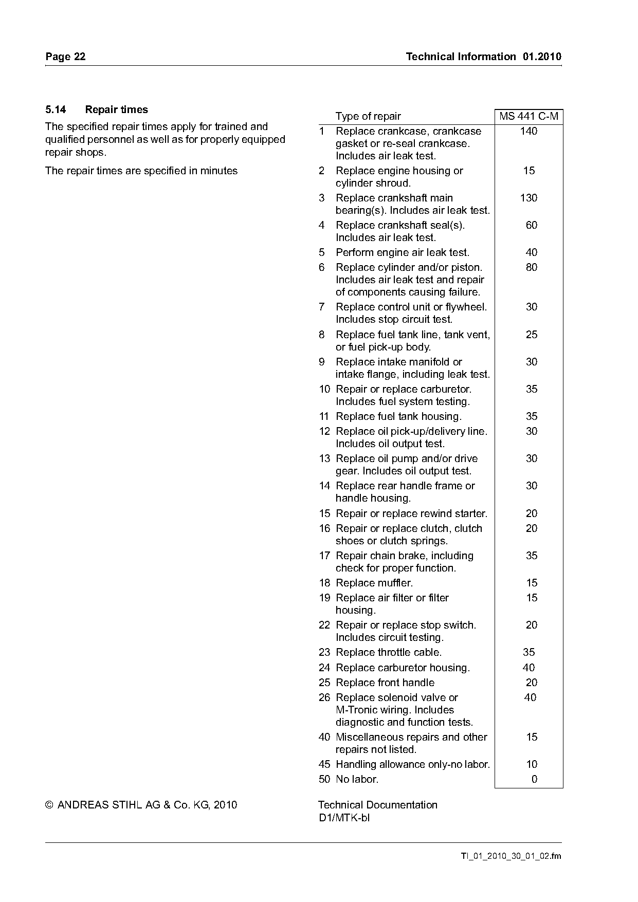
5.14    Repair times
                                                          Type of repair                      MS 441 C-M
The specified repair times apply for trained and       1 Replace crankcase, crankcase            140
qualified personnel as well as for properly equipped      gasket or re-seal crankcase.
repair shops.                                             Includes air leak test.
The repair times are specified in minutes              2 Replace engine housing or                15
                                                          cylinder shroud.
                                                       3 Replace crankshaft main                 130
                                                          bearing(s). Includes air leak test.
                                                       4 Replace crankshaft seal(s).              60
                                                          Includes air leak test.
                                                       5 Perform engine air leak test.            40
                                                       6 Replace cylinder and/or piston.          80
                                                          Includes air leak test and repair
                                                          of components causing failure.
                                                       7 Replace control unit or flywheel.        30
                                                          Includes stop circuit test.
                                                       8 Replace fuel tank line, tank vent,       25
                                                          or fuel pick-up body.
                                                       9 Replace intake manifold or               30
                                                          intake flange, including leak test.
                                                       10 Repair or replace carburetor.           35
                                                          Includes fuel system testing.
                                                       11 Replace fuel tank housing.              35
                                                       12 Replace oil pick-up/delivery line.      30
                                                          Includes oil output test.
                                                       13 Replace oil pump and/or drive           30
                                                          gear. Includes oil output test.
                                                       14 Replace rear handle frame or            30
                                                          handle housing.
                                                       15 Repair or replace rewind starter.       20
                                                       16 Repair or replace clutch, clutch        20
                                                          shoes or clutch springs.
                                                       17 Repair chain brake, including           35
                                                          check for proper function.
                                                       18 Replace muffler.                        15
                                                       19 Replace air filter or filter            15
                                                          housing.
                                                       22 Repair or replace stop switch.          20
                                                          Includes circuit testing.
                                                       23 Replace throttle cable.                 35
                                                       24 Replace carburetor housing.             40
                                                       25 Replace front handle                    20
                                                       26 Replace solenoid valve or               40
                                                          M-Tronic wiring. Includes
                                                          diagnostic and function tests.
                                                       40 Miscellaneous repairs and other         15
                                                          repairs not listed.
                                                       45 Handling allowance only-no labor.       10
                                                       50 No labor.                                0

© ANDREAS STIHL AG & Co. KG, 2010                      Technical Documentation
                                                       D1/MTK-bl

                                                                                    TI_01_2010_30_01_02.fm
Most of these PDFs embed fonts with a shifted character map, so the text above was recovered rather than copied — read it as a faithful but imperfect transcription, and treat the page image above each block as the authority where the two disagree — the figures exist only there, because they are vector drawings that text extraction cannot keep.